Projects · Mini Hostpapa
CloudStack Network Requirements & IP Plan
The four CloudStack traffic types, physical networks and traffic labels, KVM bridges, VLAN and VXLAN isolation, system VM needs, the port matrix, and the completed zone IP plan for tunisia-maghreb-1.
CloudStack Network Requirements & IP Plan
This is the document where the previous four get graded.
Everything we built in Docs 1 through 4 was network engineering that any hosting provider would recognize. Now we hand that network to a specific piece of software with specific opinions, and the software does not care how elegant our design is. It cares whether a bridge exists with the exact name we typed into a text field.
Apache CloudStack is an IaaS control plane, not a network builder. It will happily accept a zone definition that looks completely correct, launch the installer, report success, and then fail in ways that make you question your career choices. The community's own troubleshooting guidance is refreshingly blunt about the cause: in the vast majority of cases, the problem turns out to be the switching layer configured incorrectly.
CloudStack does not create the physical bridges on your hypervisors. You create them, by hand or by automation, before you add the host. If your traffic label points at a bridge that does not exist, nothing helpful happens. No error that names the problem, no validation at zone creation, just system VMs that never come up and logs that describe symptoms rather than causes.
So this document has exactly one job: take the design from Docs 2, 3, and 4 and translate it into precisely what CloudStack expects, before anybody runs an installer. Every claim in here is checked against the official Apache CloudStack documentation, and where the documentation contradicts the folklore you will find on forums, I say so explicitly.
The previous four documents taught concepts. This one is a specification. It is the least poetic document in the volume and the most valuable, because it is the one you will have open on a second monitor on install day.
I have written it so that every section ends with a decision or a filled in value, not with a discussion. By the last section you will hold a complete, defensible IP plan for the tunisia-maghreb-1 zone that you can hand to somebody else and they can build it.
Where this sits relative to Volume 4
| This doc (Volume 1) | Volume 4 |
|---|---|
| What the network must provide before installation | Installing and operating the management servers and agents |
| Traffic types, labels, bridges, IP ranges, ports | Zones, offerings, templates, accounts, quotas |
| Design decisions and the filled IP plan | Terraform resources and GitOps pipelines that apply them |
| Why a design fails CloudStack's assumptions | Day two operations, HA, maintenance, upgrades |
1. The four traffic types, precisely
The analogy: four separate mail services sharing one building
Imagine an office building with four distinct kinds of delivery moving through it. Internal memos between departments. Customer packages going in and out to the street. Post between the building and the outside world for the front desk. And bulk pallets of stock arriving at the loading dock.
You could physically run all four through the same front door. It would work, right up until the day the loading dock delivery blocks the ambulance. So a well run building separates them by route, even when they share the same street outside.
CloudStack does exactly this, and it insists on you naming which route is which.
A traffic type in CloudStack is a category of network traffic that the platform knows how to route differently. It is not a VLAN, not a subnet, and not an interface. It is a label in CloudStack's own model.
Each traffic type gets attached to a physical network, and each physical network gets connected to a real interface on the hypervisor through a traffic label. Three layers of indirection, which is exactly why it is confusing the first time and exactly why it is flexible once you see it.
The four, and what each one really carries
| Traffic type | What actually flows on it | Who talks on it |
|---|---|---|
| Management | Host to management server, host to host, system VM to management server, and DHCP for the system VMs | Hypervisors, management servers, system VMs |
| Guest | Instance to instance traffic inside tenant networks | Customer instances and their Virtual Router |
| Public | Instance to internet traffic, routed through the Virtual Router. Public IPs land on the public interface of system VMs, including Virtual Routers | Virtual Routers, secondary storage VM, console proxy VM |
| Storage | Secondary storage traffic only. Templates, ISOs, and snapshot movement performed by the secondary storage VM | Secondary storage VM and the secondary storage server |
Read that last row again. The traffic type is called Storage, and it has nothing to do with primary storage.
The official documentation is unambiguous on this point: while labeled storage, this is specifically about secondary storage traffic, and it does not affect traffic for primary storage.
Here is how I finally got this straight in my head: the Storage traffic type exists because a system VM needs a network interface to talk to the NFS export. The secondary storage VM is a virtual machine, so CloudStack has to give it a NIC, so CloudStack needs to know which network that NIC lives on. That is the whole reason the traffic type exists.
Primary storage never needs this, because primary storage is mounted by the hypervisor itself, using whichever host interface happens to share the storage subnet. CloudStack tells the hypervisor to mount it. CloudStack does not carry the bytes and does not need a traffic type for it.
The correction that saves days of confusion
If you take one thing from this section, take this. The chain of responsibility is:
Primary storage: the hypervisor mounts it directly. Route selection is ordinary Linux routing on the host, decided by which host interface shares the storage CIDR. CloudStack is not in the path.
Secondary storage: the secondary storage VM mounts it. That is a VM, so it needs a NIC, so CloudStack picks the network from the Storage traffic type if you defined one, and from the Management network if you did not.
This single distinction explains why our storage design in section 8 looks the way it does, and why a mistake here produces "primary storage is slow" rather than "primary storage is broken".
The routing subtlety almost everyone misses
Here is a documented behaviour that catches people who build a beautifully isolated storage network and then wonder why nothing works.
Straight from the official topology requirements: the secondary storage NFS export is mounted by the secondary storage VM, and secondary storage traffic goes over the management traffic network, even if there is a separate storage network. Primary storage traffic goes over the storage network, if one is available.
The consequence you must design for: if you decide to put your secondary storage NFS server on the storage network, you must make sure a route exists from the management network to the storage network.
At first I found this completely backwards, and here is the trick that made it click: the secondary storage VM's default home is the management network, because that is where every system VM has to live in order to reach the management server. Giving it a second NIC on the storage network is an addition, not a relocation. So if the NFS box is only reachable on the storage side, the traffic that starts on the management side has to be routed there. It is not a bug. It is the consequence of the system VM being a management network citizen first.
This is precisely why our storage VLAN 30 in Doc 3 has no gateway, deliberately, and why we will keep secondary storage reachable from the management network instead. Section 8 has the full reasoning.
The recommendation the documentation states plainly
The CloudStack documentation says it directly and repeats it: we strongly recommend the use of separate NICs for management traffic and guest traffic.
The reason is not performance in the first instance. It is blast radius. A customer instance saturating the guest network should never be able to starve the channel that the management server uses to tell hosts what to do. If the control plane and the tenant data plane share a wire, then a noisy tenant becomes a platform outage.
This maps exactly onto our two bond design from Doc 3: bond0 for management, bond1 for everything tenant facing.
The screenshot that explains the whole model
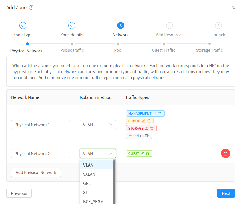
Stop and read that screenshot properly, because it is the entire section in one picture. Physical Network 1 carries MANAGEMENT, PUBLIC and STORAGE. Physical Network 2 carries GUEST. Each physical network has its own isolation method dropdown, and the open dropdown shows you the real list of choices: VLAN, VXLAN, GRE, STT and BCF_SEGMENT.
Notice what is not on that screen. There is no field for primary storage. There is no field for out of band management. CloudStack only models what CloudStack routes. Everything else is our problem, which is exactly why Doc 3 existed.
Our mapping, filled in
Here is the table that Volume 4 will consume. Every value in it traces back to a decision already made in Doc 3.
| CloudStack traffic type | Physical network | VLAN | Subnet | Bridge (traffic label) | Host interface |
|---|---|---|---|---|---|
| Management | pn-infra | 20, untagged on the host | 10.50.0.0/24 | cloudbr0 | bond0 |
| Public | pn-tenant | 40, tagged by CloudStack | 203.0.113.0/24 | cloudbr1 | bond1 |
| Guest | pn-tenant | 100 to 999, tagged by CloudStack | Per network, from 10.1.0.0/16 | cloudbr1 | bond1 |
| Storage | Not defined. Rides the management network by design | 20 | 10.50.0.0/24 | cloudbr0 | bond0 |
This is a decision, not an omission, and it deserves the reasoning written down.
Defining a Storage traffic type means the secondary storage VM gets an extra NIC on a separate network, which means another bridge on every host, another VLAN in the trunk, and another failure mode. In exchange you get faster template and snapshot copying on a dedicated high bandwidth path.
For a three host starter zone, that trade is not worth it. Template copies happen at provisioning time, not in the hot path of customer traffic, and our management network is 10 Gbps bonded. The documented default behaviour, secondary storage traffic over the management network, is exactly what we want.
The trigger to revisit: when template and snapshot operations start showing up as a measurable contributor to management network utilization, or when we add a second pod. Both are growth problems, and both are cheap to solve later. Adding a Storage traffic type to an existing zone is a supported operation. Converting a basic zone to advanced is not, which is the subject of the next section.
Meanwhile our primary storage lives on VLAN 30 at 10.50.1.0/24, mounted directly by each hypervisor over bond1.30 with a 9000 byte MTU. It appears nowhere in the table above because CloudStack does not route it. That is the whole point of section 1.
2. Basic zone versus advanced zone, decided once and forever
The analogy: choosing the foundation, not the paint
You can repaint a house. You can move a wall. You cannot change the foundation without demolishing the house.
Straight from the official docs: each zone has either basic or advanced networking, and once the choice of networking model for a zone has been made and configured in CloudStack, it cannot be changed. A zone is either basic or advanced for its entire lifetime.
There is no migration tool. There is no conversion procedure. There is no support ticket that fixes it. The remedy is build a new zone and migrate every customer into it, which for a hosting provider means a scheduled maintenance window per customer and a real risk of losing some of them.
This is the single most expensive mistake available in this entire document, and it is available on the second screen of the zone creation wizard, which is a genuinely unkind piece of interface design.
The comparison that actually matters
This is the official feature table, and I want you to read the Source NAT row twice.
| Networking feature | Basic network | Advanced network |
|---|---|---|
| Number of networks | Single network | Multiple networks |
| Firewall type | Physical only | Physical and virtual |
| Load balancer | Physical only | Physical and virtual |
| Isolation type | Layer 3 only | Layer 2 and layer 3 |
| VPN support | No | Yes |
| Port forwarding | Physical only | Physical and virtual |
| One to one NAT | Physical only | Physical and virtual |
| Source NAT | No | Physical and virtual |
| User data | Yes | Yes |
| Network usage monitoring | sFlow or NetFlow at the physical router | Hypervisor and Virtual Router |
| DNS and DHCP | Yes | Yes |
Why a hosting provider chooses advanced, in one paragraph
Look at the Source NAT row. Basic networking has none.That single cell decides the whole question for us, and here is why. In Doc 2 we established the brutal arithmetic of IPv4 scarcity: a new provider realistically gets a /24 to a /22, which is 256 to 1024 addresses, total, forever. Source NAT is the mechanism that lets many instances share one public address for outbound traffic. Without it, every instance that needs to reach the internet needs its own public IPv4 address.
Do the counting. A /24 without source NAT serves roughly 250 instances in the entire zone. The same /24 with source NAT serves hundreds of customers, each with a NAT address and optional extra addresses sold as a paid add on. It is not a performance difference. It is the difference between a viable business and one that runs out of inventory in month three.
Source NAT settles it, and the rest of the list confirms it:
No VPN, so no site to site connectivity product and no remote access into a customer's private network.
No VPC, so no customer with multiple tiers, no separate web and database subnets, no network ACLs between tiers.
No isolated networks, so every instance in a pod shares a single flat layer 2 domain and isolation depends entirely on layer 3 filtering.
A single flat layer 2 domain per pod, which also means each pod is a broadcast domain and therefore each pod needs its own guest IP range.
Any one of those is survivable. All of them together describe a product we cannot sell.
The security group model, and being fair to it
I do not want to be unfair to basic networking, because the model it uses is genuinely good and we will use it later in a different context.
A security group is a set of ingress and egress rules applied to a group of instances, filtering traffic based on the IP address attempting to communicate. It is layer 3 isolation: instances can sit on the same flat network and still not reach each other, because the hypervisor filters the packets.
The defaults are sensible and worth memorizing: every CloudStack account gets a default security group that denies all inbound traffic and allows all outbound traffic. Default deny inbound is exactly the posture we argued for in Doc 4.
An instance can belong to any number of security groups, and here is a constraint worth knowing before you promise anything to a customer: you can only change an instance's security groups while it is stopped. You cannot move a running instance from one group to another.
Security groups also work in advanced zones, on KVM specifically, giving isolation between guests on a single shared zone wide network. So the choice is not "advanced means VLANs and nothing else". You can run a shared network with security groups inside an advanced zone, which is a genuinely useful product tier and much cheaper on VLAN consumption.
The constraints that come with security group enabled zones
If you go down the security group path, the documented limitations are firm and they shape the product.
No VPCs and no isolated networks. In security group enabled advanced zones and in basic zones, creation of VPCs and isolated networks is not supported. This is the big one. You cannot offer a shared-network-with-security-groups tier and a VPC tier in the same zone if the zone is security group enabled.
No multiple VLAN ranges in a security group enabled shared network.
No mixed gateway or netmask. Two IP ranges with the same VLAN but a different gateway or netmask are not supported, in either security group enabled shared networks or account specific shared networks.
Security groups in advanced zones are hypervisor limited to KVM and XenServer or XCP-ng with the network backend configured as bridge. On KVM, which is our platform, this is fine.
Here is how I read those constraints as a product person rather than an engineer: enabling security groups at the zone level buys you cheap isolation and costs you the entire VPC product line. That is not a trade I want to make at zone creation, before we have a single customer, when the alternative preserves both options.
Our decision, recorded
Decision: tunisia-maghreb-1 is an advanced zone. Guest isolation method is VLAN. Zone level security groups are not enabled.
- Source NAT is mandatory given our IPv4 position from Doc 2. Basic networking does not offer it. This alone is decisive.
- VPC is a product we intend to sell, and enabling zone level security groups permanently forecloses it in this zone.
- The decision is irreversible, so we choose the option with the larger feature surface. Advanced can express everything basic can express, plus more.
- Per tenant VLAN isolation is a stronger security story than shared network filtering, and in a market where we are the new entrant, a stronger security story is worth real money. This connects directly to the tenant isolation argument in Doc 4.
What we accept in exchange: more configuration steps, a VLAN ceiling we have to plan around, and the requirement that private and public networks live in separate subnets, which advanced zones enforce. All three are handled in this document.
Cost of being wrong: if advanced turns out to be overkill, we have carried unnecessary configuration complexity. If basic turns out to be insufficient, we rebuild the zone and migrate every customer. The asymmetry of those two outcomes is the actual argument.
3. Physical networks, traffic labels, and bridges on KVM
The analogy: the label on the patch panel port
In Doc 3 we spent real effort on labelling patch panel ports, and the reason was that a cable without a label is a cable nobody will touch in six months.
A CloudStack traffic label is the same idea, pointed in the opposite direction. It is a string you type into CloudStack that says "when you need to attach something to the public network, use the thing on the host called cloudbr1". CloudStack does not inspect it, does not validate it at the time you type it, and does not create it. It just writes it down and uses it later.
There is no validation. Type cloudbr01 when you meant cloudbr1 and the zone creates successfully. The failure arrives later, when CloudStack tries to attach a system VM to a bridge that does not exist, and the message you get describes a system VM that will not start rather than a label that is wrong.
Worse, fixing the label is not enough. System VMs that were created against the broken label have to be destroyed and recreated so that CloudStack rebuilds their interfaces against the corrected value. This is why the label appears in our pre install verification gate at the end of this document.
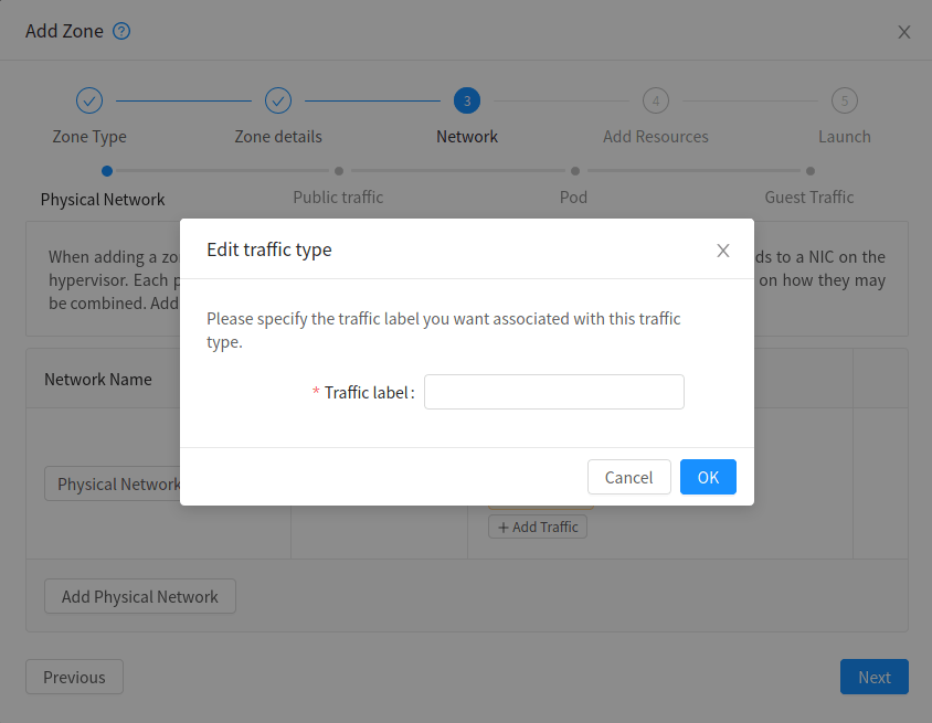
Look how small that dialog is. One field. No dropdown listing the bridges CloudStack found on your hosts, because at zone creation time CloudStack has not met your hosts yet. That is the whole reason this section exists, and the whole reason the verification step in section 11 is not optional.
What a physical network is, in CloudStack terms
A physical network in CloudStack is the actual network hardware and wiring in a zone. In the documentation's own words, the network corresponds to a NIC on the hypervisor host.
A zone can have multiple physical networks in advanced mode, and each one can carry one or more traffic types. Against each physical network you configure:
- The isolation method, which is VLAN for us
- The VLAN range available to it
- A name so hypervisors can recognize it
- The traffic types it carries
- The service providers available on it, such as firewalls and load balancers
There is one rule about multiple physical networks that bites people who discover it after the fact:
You can configure a zone with multiple physical networks carrying the guest traffic type. In such zones, you must tag the additional physical networks.
And the rule that follows: you must have one physical network that is not tagged, so that isolated and layer 2 network offerings which are not configured with any tags still work. The default network offerings fall into exactly that category.
At first I found this confusing because the word tag is doing double duty, and here is the trick: the VLAN tag is a number in an Ethernet frame. A physical network tag is a text string CloudStack uses to match a network offering to a physical network. They are unrelated concepts that share a word. If a network offering has no tag, CloudStack needs an untagged physical network to put it on, and if every physical network is tagged, the default offerings have nowhere to go.
Bridge naming: what is convention and what is enforced
A bridge is a software switch inside the Linux kernel. It has ports, it learns MAC addresses, and it forwards frames between its ports exactly like the physical switch in Doc 3, except it exists in software on the host.
Why this matters for virtualization: a VM's virtual NIC has to plug into something. It plugs into a bridge. The bridge also has the host's physical interface as a port, which is what connects the VM to the outside world. The bridge is the patch panel inside the server.
Now the important distinction, because two facts here look similar and only one of them is enforced.
| Rule | Convention or enforced? | What happens if you break it |
|---|---|---|
Bridges named cloudbr0, cloudbr1 and so on | Convention. The docs say by default these bridges are called cloudbr0 and cloudbr1, and that this can be changed to be more descriptive | Nothing, as long as your traffic label matches the name you chose |
| The underlying interface name matches a recognized pattern | Enforced. This one is a hard constraint | The KVM agent cannot configure the bridges properly. Not a warning, a functional failure |
| Bridge to NIC mapping identical on every host in a cluster | Enforced by consequence. The docs say it is essential that you keep the configuration consistent across all of your hypervisors | Live migration fails, or worse, succeeds and attaches to the wrong network |
The interfaces used to configure the bridges must match one of these patterns:
eth*, bond*, team*, vlan*, em*, pp, ens*, eno*, enp*, enx*
Otherwise the KVM agent will not be able to configure the bridges properly.
Why our design is already safe: we use bond0 and bond1, which match bond*, and the VLAN sub interfaces CloudStack creates come out as bond1.40 style names which match vlan* handling. This is not luck. It is one of the reasons Doc 3 chose bonded interfaces with predictable names instead of renaming NICs to something friendly like mgmt0.
And that is the actual lesson here: the temptation to rename interfaces to something human readable is strong, and on a CloudStack KVM host it is a trap. Keep the boring names.
The reference two NIC advanced zone layout
This is the layout the CloudStack documentation itself describes for advanced networking, and it is worth understanding why it is shaped this way rather than just copying it.
| Interface | Bridge | VLAN handling | IP address | Carries |
|---|---|---|---|---|
bond0 | cloudbr0 | Untagged, the native VLAN | Yes, the hypervisor's own management IP | Management traffic |
bond1 | cloudbr1 | None configured by us. CloudStack adds VLAN sub interfaces on demand | No IP address at all | Public and guest traffic |
cloudbr0 holds the host's IP, cloudbr1 holds none.The host needs an address to be managed. It does not need an address on the tenant side, and giving it one would be actively bad: it would place the hypervisor itself inside a network that customer traffic traverses. A bridge with no IP address is a bridge the host cannot be attacked through. This is the same reasoning as the deliberately gateway-less storage VLAN in Doc 3.
Detail two: we configure no VLANs onbond1, on purpose.The documentation is explicit that in the advanced layout, there are no VLANs applied by us on the second interface, because CloudStack will add the VLANs as required during actual use.
When a customer creates a guest network and CloudStack assigns it VLAN 137, the KVM agent creates bond1.137 and a bridge for it, on the fly, on whichever hosts need it. If we had pre created those interfaces we would be fighting the agent for ownership of them.
What this means for the switch, and it is the punchline of Doc 3: because CloudStack tags on demand and can pick any VLAN in the configured range, the entire guest VLAN range must be trunked to every host, in advance. The switch cannot be configured reactively. This is why our ToR trunk carries 100 to 999 on every host port even though only a handful are in use today.
cloud0, the bridge nobody tells you about
cloud0 is a host only bridge on link local address space that exists so the hypervisor can talk to the system VMs running on it, over a channel that does not depend on any of the production networks working.
Think of it as the intercom between the building manager and each apartment, separate from the phone lines the residents use. If the tenant network is broken, the manager can still knock.
On KVM, CloudStack normally creates cloud0 for you. It is the one bridge in the whole design where the correct instruction is usually to leave it alone rather than to build it. The exception, and the reason it is worth knowing the name: if you are building hosts from an image or under strict automation where CloudStack's agent cannot create it, you pre create it yourself, empty, on link local space.
You will meet cloud0 again in section 6, because it is how you get an SSH session into a system VM, and in section 7, because it explains why the host does not need inbound firewall rules for the system VM control channel.
Our bridge build, and what it looks like on the host
One. cloudbr0 has an IP and cloudbr1 does not. If you find an address on cloudbr1, somebody made a mistake.
Two. bond1.30 for primary storage is created by us, not by CloudStack, and it is the only VLAN sub interface on bond1 that we own. Everything else on bond1 belongs to the agent. This is the boundary that section 8 depends on.
Three. cloud0 connects to nothing outside the host. If it appears in a switch configuration, somebody has misunderstood it.
Verification: compare what CloudStack believes against what exists
The whole point of this section is that CloudStack's model and the host's reality can disagree silently. So we check.
Command one proves the three bridges exist and are up. If cloudbr1 were missing here, the zone would create successfully and the first customer network would fail.
Command two proves the bridges have the right members. A bridge can exist and be completely empty, which is a failure that command one cannot see. Notice master cloudbr0 against bond0: that is the enslavement we need, and state forwarding means it is actually passing frames rather than blocked by spanning tree.
Command three is the one I care about most, and it is the one people skip. cloudbr0 has 10.50.0.101/24. cloudbr1 has nothing after UP, which is exactly right. An empty address column on cloudbr1 is a passing test, and it looks like a broken command. That is why I am pointing at it.
Run this on every host and diff the output. Identical except for the last octet is what correct looks like.
4. Isolation methods: VLAN, VXLAN, and the rest
The analogy: floor numbers versus GPS coordinates
A VLAN tag is like a floor number in a building. It is short, it is cheap, everybody understands it, and there is a hard limit on how many floors your building has.
A VXLAN identifier is like a full postal address written inside an envelope that gets carried by the ordinary mail. It is longer, it costs more to carry, and there is effectively no limit on how many addresses exist.
Both deliver the letter. One of them runs out.
VLAN, and the ceiling we have to plan around
The VLAN tag is 12 bits. That is the whole story of the constraint.

Find the VID field in the bottom frame. That single field is the entire scalability limit of VLAN based isolation. Twelve bits gives 4096 values, two are reserved, so you get roughly 4094 usable VLAN IDs across the whole layer 2 domain. Not per switch. Not per host. Per broadcast domain.
In CloudStack's isolated network model, each guest network consumes exactly one VLAN. So the guest VLAN range you set at zone creation is a direct, hard cap on how many guest networks can exist simultaneously in that zone.
The zone level guest VLAN range is set at zone creation, in the Guest Traffic step of the Add Zone wizard. It is one field, a start and an end.
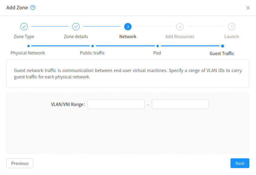
The same field carries the VLAN range in a VLAN zone and the VNI range in a VXLAN zone. CloudStack treats them as the same kind of thing, which is a segment identifier, and only the isolation method on the physical network decides how it is used.
This is genuinely useful to know, and here is why: it means the mental model does not change when you migrate to VXLAN later. You are still allocating segment identifiers from a range. You are just allocating from a range with 16 million values instead of 4094. The concept is stable across the migration, which makes the migration a lot less frightening than it sounds.
The tradeoff CloudStack exposes, and the numbers you must choose
There is a global setting in CloudStack that governs how the platform partitions its internal identifier space, and it forces a choice: a higher ceiling on VLANs per zone means a lower ceiling on running instances per zone, and vice versa.
You do not get both maxed out. The default favours instance count, which is correct for the majority of deployments and is not necessarily correct for a per tenant VLAN product model, where VLAN consumption grows with customer count rather than with instance count.
The action item: decide this deliberately, at zone creation, based on how you sell. If every customer gets an isolated network, then customers times one VLAN is your growth curve, and you need to check that ceiling against your three year business plan before it becomes an emergency. Verify the current setting name and default against your exact CloudStack version, because this is the kind of internal setting that gets adjusted between releases.
Our VLAN counting, done honestly
| Quantity | Value | Where it comes from |
|---|---|---|
| Total usable VLAN IDs | 4094 | Twelve bit VID, two reserved values |
| Reserved for infrastructure | 10, 20, 30, 40, 50 | OOB, management, storage, public, DMZ from Doc 3 |
| Left unused deliberately | VLAN 1 | Default on every switch, so mistakes land there and reach nothing |
| Guest VLAN pool | 100 to 999 | Configured at zone creation |
| Simultaneous guest networks possible | 900 | One VLAN per isolated network |
| Headroom above the pool | 1000 to 4094 | Available but not configured. Expanding the range later is a supported change |
900 guest networks is comfortably beyond the starter business plan, and it is emphatically not unlimited. When we approach it, the answer is not a bigger VLAN range, because past 4094 there is no bigger range. The answer is VXLAN.
VXLAN, and what it actually costs
VXLAN takes a complete Ethernet frame, wraps it inside a UDP packet, and ships it across an ordinary routed IP network to another host, which unwraps it and delivers the original frame.
The consequence that matters: your layer 2 segment is no longer limited by where your layer 2 domain physically reaches. It can span racks, rows, and routed boundaries, because the transport underneath is plain IP.
Here is the sentence that made it click for me: VLAN asks the switches to remember which segment a frame belongs to. VXLAN writes the segment identifier into the packet itself and lets the switches do nothing but route IP. That is why it scales. The state moves from the network into the packet.
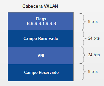
Compare that diagram against the 802.1Q one above and the whole argument is visible. The 802.1Q VID is 12 bits, giving 4094 segments. The VXLAN VNI is 24 bits, giving roughly 16.7 million segments. That is the upgrade, and the eight byte header in that picture is part of what it costs you.
A VTEP, VXLAN tunnel endpoint, is the thing that does the wrapping and unwrapping. On our platform that is the KVM host itself, in the Linux kernel.
Each VTEP needs its own IP address, which is how the other VTEPs find it. The overlay networks ride between VTEPs, and the physical network in between only ever sees UDP packets between host IP addresses.
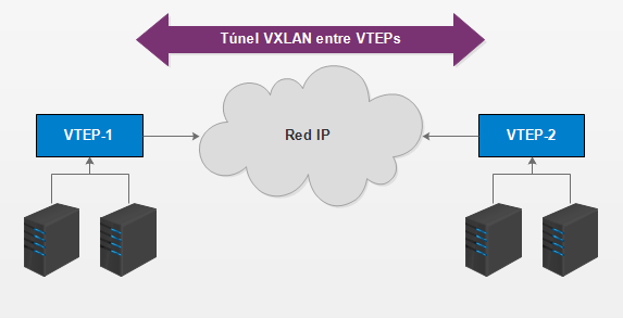
The servers on the left and the servers on the right believe they are plugged into the same switch. They are not. There is a routed IP network between them, and it has no idea those segments exist. That illusion is the product VXLAN sells, and everything else in this section is the price.
VXLAN requirements, exactly as documented
| Item | Requirement | Note |
|---|---|---|
| Hypervisor | KVM only | Only the default BridgeVifDriver is supported, meaning Linux bridge, not OpenVSwitch |
| Network card | VXLAN offloading recommended | Documented examples are Mellanox ConnectX-5 and Intel X710 |
| IP protocol | IPv4 or IPv6 | CloudStack is agnostic to the underlay protocol. Both are supported |
| MTU | 1550 minimum | VXLAN has 50 bytes of overhead, so 1550 is the floor. See the arithmetic below |
| BGP routing daemon | FRRouting version 10 or higher | Only required for EVPN mode. Not needed for multicast mode |
This is worth working through slowly because getting it backwards produces the single most annoying class of bug in networking: everything works except large transfers.
When a VXLAN interface is created, the kernel reads the current MTU of the physical interface or bridge and creates the VXLAN interface exactly 50 bytes smaller. The subtraction happens automatically, and it happens downward from the parent.
So the chain is:
Physical interface at 1500, the ordinary default, gives you a VXLAN interface at 1450. Your customer's instance now has 1450 bytes available and any software assuming 1500 starts producing mysterious stalls.
Physical interface at 1550 gives you a VXLAN interface at exactly 1500. This is the documented minimum, and it means normal instances see a normal MTU.
Physical interface at 9000 gives you a VXLAN interface at 8950, and instances can be set to 8950.
Physical interface at 9216 gives you 9166, which comfortably contains a clean 9000 byte jumbo frame inside guest networks.
The documented recommendation: use an MTU of at least 9000 and preferably 9216, since most VXLAN capable cards and switches support up to 9216.
At first I found this backwards and here is the trick I use to keep it straight: the overlay is a passenger inside the underlay, so the passenger is always smaller than the vehicle. You never raise the overlay MTU. You raise the underlay MTU and the overlay follows, 50 bytes behind, forever.
VXLAN mode one: multicast
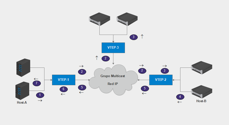
Follow the numbered arrows and you can see both the elegance and the problem. When VTEP-1 does not know where a destination lives, it sends the frame to a multicast group that every VTEP in that segment has joined. Every VTEP receives it. Only the one holding the destination answers. It is exactly the flooding behaviour of an ordinary switch, implemented with IP multicast instead of with copper.
| Aspect | Multicast mode |
|---|---|
| Setup difficulty | The easiest way to get VXLAN isolation working |
| Network requirement | Hosts must reach each other by IP multicast on UDP port 8472 |
| Host addressing | An IPv4 address on a physical or bridge interface to originate and terminate VXLAN traffic. It does not have to be the same subnet on every host |
| Traffic label | The name of the physical interface, or a bridge bound to it. A bridge is useful when interface names differ per host |
| Firewall | UDP 8472 must be permitted |
This one deserves its own callout because the failure message tells you nothing about the cause.
Every multicast based VXLAN interface joins a multicast group. The kernel parameter net.ipv4.igmp_max_memberships controls how many multicast groups a host may join, and its default value is 20.
So on a default Linux host you cannot start more than 20 VXLAN interfaces. Attempt 21 and the CloudStack agent log shows:
No buffer space availableThat message says nothing about multicast, nothing about VXLAN, and nothing about a limit. It reads like memory exhaustion, which sends you looking in entirely the wrong place. I am flagging it here so that if you ever see it, you already know the answer.
The fix is to raise the parameter to something appropriate such as 100 or 200. The documentation states it plainly: if you need to operate instances from more than 20 different client networks on a host, this change is required.
And here is the business consequence: 20 networks per host is far below any interesting density for a hosting provider. This is not an optimization. It is a mandatory step, and it belongs in host build automation rather than in a runbook a human might skip.
Command one shows the default of 20, unchanged, which is what a fresh host looks like.
Command two writes it into /etc/sysctl.d/ rather than setting it with a bare sysctl -w. That distinction matters: a bare sysctl -w survives until the next reboot, and then your VXLAN capacity silently drops back to 20 at the worst possible moment. Persistence is the entire point of doing it this way.
Command three counts the VXLAN interfaces currently present, and 0 is the correct answer on a host that has no guest networks placed on it yet. It is a baseline you can compare against after the first tenant network lands.
VXLAN mode two: EVPN with BGP
This is the scale path, and the documentation is unusually candid about it: deploying VXLAN, especially with EVPN, requires extensive networking knowledge, which is not covered by CloudStack documentation or CloudStack in general. I appreciate that honesty and I am going to repeat it.
| Requirement | Detail |
|---|---|
| Routing daemon on hypervisors | FRRouting recommended, version 10 or higher. It runs BGP on the hypervisor itself |
| Tunnel source | An IPv4 /32 configured on the loopback interface, which becomes the VTEP source address |
| No bonding | No LACP or bonding is used. Instead each host runs two BGP sessions to two top of rack switches |
| UDP port | 4789, the RFC 7348 assigned port, instead of 8472 |
| Learning mode | VTEP devices are created with nolearning, which disables the use of multicast entirely |
| Script change | A symlink on each hypervisor pointing modifyvxlan.sh at the shipped modifyvxlan-evpn.sh |
| Upstream network | Must be BGP and EVPN capable, with each host establishing eBGP to its ToR devices, which connect to spines that terminate the VNIs and act as gateways |
| Per host ASN | Each hypervisor gets its own unique AS number |
Everything else in that table is configuration. This one is architecture, and it directly contradicts the bonded design we built in Doc 3.
Here is the reasoning, and once I understood it I stopped resenting it: bonding solves link redundancy at layer 2. The two physical links pretend to be one logical link, and the switches cooperate to make that work, which is where MLAG comes from and where a good deal of vendor specific complexity lives.
EVPN solves the same problem at layer 3. Instead of two links pretending to be one, you run two independent BGP sessions over two independent links to two independent switches. If a link dies, BGP withdraws the routes through it and traffic uses the other. No MLAG, no vendor cooperation between switches, no shared state between them at all.
It is a strictly better failure model, because there is no shared control plane between the two switches to go wrong. It is also a completely different rack build, a different switch configuration, and a different skill set to operate.
Which is exactly why we start with VLAN. Not because VXLAN with EVPN is wrong. Because it is a project, and projects need to be scheduled rather than discovered.
The documentation states this as a warning and so will I: VNI must be unique per zone and no duplicate VNIs can exist in the zone. Exercise care when designing your VNI allocation policy.
With 16.7 million values available, the temptation is to allocate carelessly. Do not. Design the allocation scheme before you need it, ideally encoding meaning into the number, for example a range per pod or a range per product tier. A flat sequential allocation is the option that works fine until you need to reason about it during an incident.
GRE and layer 3 isolation: the honest assessment
You saw them in the dropdown screenshot: alongside VLAN and VXLAN there are GRE, STT, and BCF_SEGMENT.
These isolation methods are accepted by the API and present in the interface, and their supporting documentation is thin to absent in current releases. Several of them exist because of SDN integrations, some of which are no longer actively maintained.
Here is my honest position, stated as a rule I apply generally: for a new production build, an option with no current documentation is not an option. Not because it cannot work, but because when it breaks at two in the morning there is nothing to read and nobody to ask. The value of VLAN and VXLAN is not only technical. It is that thousands of operators run them and write about them.
Choose the boring, well documented, widely deployed thing. Save your novelty budget for the parts of the product that customers actually pay for.
Our decision, with the trigger conditions written down
Decision: guest isolation is VLAN, guest VLAN range 100 to 999, giving 900 simultaneous guest networks in tunisia-maghreb-1.
- 900 networks exceeds the three year plan, and the counting is written in the table above rather than asserted.
- The ToR switch already trunks it, per Doc 3. Zero additional hardware.
- MTU stays simple. No 50 byte overhead, no overlay arithmetic, no jumbo frame dependency for tenant traffic.
- It is the CloudStack default, which means it is the best tested path and the one that forum answers actually describe.
- Guest VLAN utilization crosses 600 of the 900, which is two thirds and leaves real time to execute
- A second pod is planned in a way that makes stretching layer 2 between racks necessary
- A customer requirement appears that needs a segment to span a routed boundary
- We add a second zone and want a consistent overlay model across both
What the project must include on day one, so it is not discovered mid-flight: raising igmp_max_memberships if multicast, or the full FRRouting and per host ASN build if EVPN. Underlay MTU raised to 9216. A VNI allocation scheme designed before the first VNI is issued. And if EVPN, the rebuild of host connectivity from bonded to dual BGP sessions, which is the expensive part and the reason this is a project rather than a change.
Notice what that decision record does that a simple choice would not. It states the choice, it states the counting behind the choice, it states the numeric threshold that invalidates the choice, and it states what the replacement costs. That is what makes it a decision somebody can inherit rather than a preference somebody has to re-litigate.
5. Zone, pod, and cluster mapped to real IP ranges
The analogy: country, city, street, building
CloudStack's hierarchy is a nesting doll, and each layer constrains something real.
| Level | Analogy | What it actually constrains |
|---|---|---|
| Region | Country | The largest organizational unit. Each region has its own cluster of management servers. Accounts span regions |
| Zone | City | Typically one datacenter. Own power and network uplink. Secondary storage is zone wide. Basic or advanced is fixed here, forever |
| Pod | Street | Usually a single rack. Hosts in the same pod are in the same subnet. Not visible to end users |
| Cluster | Building | A set of homogeneous hosts sharing primary storage. Live migration happens within a cluster, not across them |
| Host | Apartment | One hypervisor. Smallest unit. Invisible to end users, who cannot tell which host they landed on |
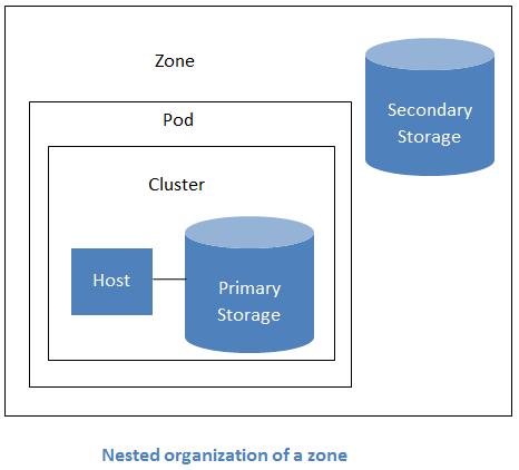
Look where the two storage cylinders sit in that picture, because the placement is the specification. Primary storage is inside the cluster, next to the host, because the host mounts it. Secondary storage is outside the pod, at zone scope, because every pod in the zone shares it. That is not a drawing convention. It is why primary storage is a cluster resource in CloudStack's model and secondary storage is a zone resource, and it is why they need different network treatment.
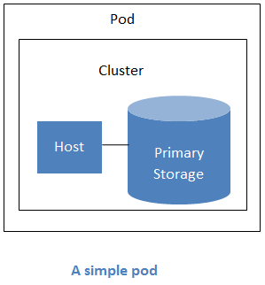
The pod rule that shapes all our addressing
This one sentence from the documentation drives the entire management IP plan: hosts in the same pod are in the same subnet.
The consequence, stated as a design rule: your pod boundary is your management subnet boundary. One pod, one management subnet. When you add a second pod, you add a second management subnet, and it needs a route to the first one, which brings us to the console proxy requirement in section 6.
Here is the thing I find genuinely elegant about this constraint: it means CloudStack's logical hierarchy and your physical rack layout naturally line up, because a rack is a switch is a subnet is a pod. Doc 3 built one rack. So we build one pod. The model and the metal agree, and when they agree, nobody has to hold a translation table in their head during an incident.
Cluster homogeneity requirements
The documented requirements, and each one exists for a reason worth knowing:
Identical hardware and the same hypervisor. Because the cluster is the live migration boundary.
The same subnet. Which follows from the pod rule above.
Access to the same shared primary storage. Because a migrating VM's disk must be reachable from the destination host, and copying it would not be a live migration.
Comparable CPU features. This is the one that bites in practice. A VM migrated onto a host lacking a CPU feature the guest is already using does not degrade gracefully, it crashes. This is also why the CPU mode setting matters: host-passthrough gives the best performance and can cause migration failure, while host-model is the safer default for a homogeneous cluster.
A pinned architecture in recent versions, which means you cannot mix x86_64 and ARM hosts in one cluster.
The practical procurement lesson, and it is worth real money: buy hosts for a cluster in one purchase order, from one batch. The moment you add a host eighteen months later with a newer CPU stepping, you are choosing between a degraded CPU mode across the whole cluster or a second cluster. Both are fine. Discovering the choice while unboxing the server is not.
Reserved system IP range, and the rules that bite
This is a range of addresses, configured per pod, that CloudStack reserves for itself. It must be a subnet of the management physical network.
What lives in it: the system VMs. Secondary storage VMs, console proxy VMs, and the DHCP function. The documentation describes it as carrying communication between the management server and the various system VMs.
Here is the mental model that made this stop being confusing for me: it is a DHCP pool that CloudStack owns. Everything else in the management subnet is statically assigned by you. This range is the part you hand over to the platform and promise never to touch.
Three rules, and every one of them has produced a real outage somewhere.
| Rule | What goes wrong if you break it |
|---|---|
| Reserved system IPs must be unique across the entire cloud | The docs are explicit: you cannot have a host in one zone with the same private IP as a host in another zone. Break this and you get conflicts that appear only when the two zones need to talk |
| Management servers and hypervisors must sit outside the reserved range | CloudStack will hand a system VM the address your management server is using. The documented example is a reserved range of .2 to .7, leaving .8 to .254 for the management server and hosts |
| Size it with growth headroom | The recommendation is roughly one private IP per host, plus in advanced zones about ten more for the system VMs. Undersize it and you cannot start a system VM, at which point templates stop downloading and consoles stop working |
Here is a genuine architectural gift that KVM gives you and some other hypervisors do not.
On KVM and XenServer, virtual routers use link local addressing for their control interface. The documentation notes this in theory provides more than 65,000 private addresses within the address block.
Compare that to VMware ESXi, where the documentation warns that an administrator typically provides only 255 IPs per pod, shared between physical machines, guest virtual routers, and other entities, so it is possible to run out of private IPs when scaling up a pod. The documented workarounds are to use a larger CIDR such as a /20, or to create multiple pods.
So on KVM, every Virtual Router you create costs you zero management addresses. Only the SSVM, the CPVM and the hosts consume from the pod subnet. That is why a /24 per pod is genuinely comfortable for us and would be tight on ESXi. It is a small detail that makes the address plan below much less stressful than it would otherwise be.
Public IP ranges, and what CloudStack lets you do with them
Multiple public IP ranges are allowed per zone. Each range is defined by a VLAN ID, an IP range, and a gateway, and the administrator may provision many of them.
More usefully for a commercial product: ranges can be dedicated to a specific account. You can reserve a VLAN range and a public IP range from an advanced zone and assign it to one account, then disassociate it later.
There are two global settings that govern what happens when a dedicated account exhausts its allocation, use.system.public.ips and use.system.guest.vlans. By default an account that has consumed everything dedicated to it can still acquire more from the system pool, and these settings let the root admin disallow that. Both are configurable at the account level.
That second paragraph is a commercial control disguised as a technical setting. If you sell a customer a dedicated block, the default behaviour lets them quietly spill into your shared pool once they exhaust it, which is inventory leaking out of the product you are selling. Setting these to false per account is how a dedicated allocation actually stays a dedicated allocation.
The completed IP plan for tunisia-maghreb-1
Here it is, filled in. This is the deliverable of the whole document.
The public IPv4 space below uses 203.0.113.0/24 and the IPv6 space uses 2001:db8::/32. These are the reserved documentation ranges from RFC 5737 and RFC 3849, used deliberately so that this document can be published without exposing real allocated space. Substitute the real allocation from Doc 2 when you build. Every prefix length and every count is real.
Zone level
| Setting | Value | Justification |
|---|---|---|
| Zone name | tunisia-maghreb-1 | Matches high level architecture |
| Network type | Advanced | Decision D1-05-01. Irreversible |
| Guest isolation | VLAN | Decision D1-05-02 |
| Guest VLAN range | 100 to 999 | 900 simultaneous guest networks. Headroom to 4094 unallocated |
| Zone DNS | 10.50.0.11 and 10.50.0.12 | Internal resolvers, inside the reserved range boundary discussion below |
| Internal DNS | Same two resolvers | Used by system VMs. Must be reachable from the management network |
| Public IPv4 range | 203.0.113.32 to 203.0.113.190 | 159 usable public addresses. Gateway 203.0.113.1, netmask /24, VLAN 40 |
| Public IPv6 range | 2001:db8:0:40::/64 | Exactly a /64, no start or end addresses, same VLAN 40 as the IPv4 range. Section 9 explains why all three constraints are mandatory |
| Guest IPv6 prefix | 2001:db8:1::/48 | 65,536 guest networks worth of /64 blocks. Section 9 explains why not a /56 |
| Private ASN pool for dynamic routing | 4200100000 to 4200100999 | 1000 ASNs from the 32 bit private range. Section 10 |
Pod level: tun-pod-1
| Setting | Value | Justification |
|---|---|---|
| Pod name | tun-pod-1 | One rack, one pod, per Doc 3 |
| Pod CIDR | 10.50.0.0/24 | The management VLAN 20 subnet. Hosts in a pod share a subnet |
| Pod gateway | 10.50.0.1 | The ToR switch SVI from Doc 3 |
| Reserved system IP range | 10.50.0.20 to 10.50.0.79 | 60 addresses. Sizing worked below |
| Storage IP range | Not configured | No Storage traffic type defined. Section 1 decision |
The management subnet, address by address
This is the table that prevents the mistake. Every address in 10.50.0.0/24 is accounted for, and the reserved range is a contiguous block that nothing else touches.
| Range | Assigned to | Count | Inside reserved range? |
|---|---|---|---|
10.50.0.1 | ToR switch SVI, the pod gateway | 1 | No. Correct |
10.50.0.11 to 10.50.0.12 | Internal DNS and NTP resolvers | 2 | No. Correct |
10.50.0.20 to 10.50.0.79 | CloudStack reserved system IP range | 60 | Yes. This is the range itself |
10.50.0.101 to 10.50.0.103 | kvm-host-01, -02, -03 on cloudbr0 | 3 | No. Mandatory |
10.50.0.104 to 10.50.0.150 | Reserved for future hypervisors | 47 | No. Growth |
10.50.0.200 | Management server virtual IP, the load balanced endpoint | 1 | No. Mandatory. Section 7 explains why this address is load bearing |
10.50.0.201 to 10.50.0.202 | cs-mgmt-01 and cs-mgmt-02 | 2 | No. Mandatory |
10.50.0.210 | nfs-store-01 management interface, for secondary storage reach | 1 | No. Correct |
The documented guidance is one private IP per host, plus about ten for the system VMs, plus headroom for growth. Applied to us:
Three hosts today gives 3.
About ten for system VMs gives 10. In practice a single pod runs one SSVM and one CPVM, so this figure is mostly headroom for the platform to spin up replacements before retiring the old ones during an upgrade, which is exactly when you least want to be short.
Growth to sixteen hosts gives 16, because a 42U rack with 2U hosts and our other equipment lands somewhere around there.
Extra system VM capacity for a second cluster gives another 10.
Subtotal: 39. Rounded up with real margin: 60. Range 10.50.0.20 to 10.50.0.79.
Why round up so generously when the calculated need is 39? Because expanding a reserved system range on a live pod means touching pod configuration on a running platform, and the cost of 21 unused addresses in an RFC 1918 /24 is exactly zero. This is the one place in the entire document where being generous costs nothing, so I am generous here and disciplined everywhere the addresses are actually scarce.
And notice the gaps. There is nothing between .79 and .101, and nothing between .150 and .200. Those gaps are deliberate: they make the boundaries of the reserved range visually obvious in a routing table or an nmap scan. An address in the 80s should never appear, and if it does, somebody assigned something by hand without reading this table.
The storage subnet
| Address | Assigned to | MTU |
|---|---|---|
10.50.1.20 | nfs-store-01 storage interface, primary storage export | 9000 |
10.50.1.101 to 10.50.1.103 | Hypervisor bond1.30 interfaces | 9000 |
| Gateway | None, deliberately. This subnet does not route | Not applicable |
Notice that the storage subnet appears nowhere in CloudStack's configuration. No storage traffic type, no storage IP range in the pod. It exists purely as a Linux routing fact on each host, which is exactly what section 1 established and section 8 will justify in full.
Guest network addressing
| Setting | Value | Note |
|---|---|---|
| Guest IPv4 space | 10.1.0.0/16 | CloudStack carves a per network CIDR out of this. Default offerings typically use a /24 |
| Networks available from it | 256 at /24 each | Below the 900 VLAN ceiling, so the address space becomes the binding constraint before the VLAN range does |
| Per network gateway | First address, on the Virtual Router | The classic 10.1.1.1 pattern |
| Guest IPv6 per network | One /64 from 2001:db8:1::/48 | Assigned by CloudStack. Section 9 |
Read that second row again. The VLAN range allows 900 guest networks. The guest IPv4 space at 10.1.0.0/16 with a /24 per network allows 256.
So the real ceiling is 256, not 900, and it is set by an address plan decision rather than by the isolation method everybody argues about.
This is the trap of planning two constraints in two separate documents. The VLAN counting felt like the answer because it was the number I had just worked out in section 4, and it was the looser of the two constraints all along.
The fix is trivial once you see it: use 10.0.0.0/8 for guest space rather than 10.1.0.0/16, which gives 65,536 possible /24 networks and puts the ceiling comfortably back on the VLAN range where our section 4 counting expects it. Private IPv4 space is not scarce. Public IPv4 space is. Being frugal with RFC 1918 addresses is a habit imported from a place where it made sense, and it does not make sense here.
10.0.0.0/8, excluding 10.50.0.0/16 which is reserved for infrastructure.6. System VMs and what the network owes them
The analogy: the building staff
Every apartment building runs on people the residents rarely think about. A concierge who handles post and packages for everyone. A maintenance engineer who can get into any apartment. A caretaker for each floor who handles that floor's plumbing and lets residents in and out.
CloudStack's system VMs are exactly that staff. They are virtual machines the platform creates and manages for itself, and they have network needs that are different from, and stricter than, your customers' needs. When a customer's VM cannot reach the internet, one customer complains. When the secondary storage VM cannot reach the internet, nobody can deploy anything at all.
Virtual Router (VR). One per guest network. It is the gateway, the DHCP server, the DNS forwarder, the firewall, and depending on the offering the source NAT device, load balancer and VPN endpoint for that network.
Secondary Storage VM (SSVM). One per zone. It downloads templates and ISOs from the internet, and moves snapshots to and from secondary storage.
Console Proxy VM (CPVM). One per zone to start with. It provides browser based console access to instances, which means it needs to reach the VNC port of every VM in the zone.
The Virtual Router and its three interfaces
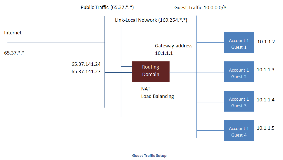
That single diagram is the most important picture in this document after the physical network screenshot. Count the vertical lines the routing domain touches: three. Public traffic, link local, and guest traffic. Three interfaces, three purposes, three completely different sets of firewall implications.
| Interface | Network | Purpose | Who may reach it |
|---|---|---|---|
eth0 | Guest, 10.1.1.1 in the diagram | The gateway for guest traffic. Also DHCP and DNS for that network | Only instances in that guest network |
eth1 | Link local, the 169.254 range | Used by CloudStack to configure the router. The control channel | Only the hypervisor hosting it. Nothing else, ever |
eth2 | Public, VLAN 40 | Carries the public IPs. Additional public interfaces appear when multiple public VLANs exist | The internet, filtered by the rules the customer configured |
Look at that middle interface again: 169.254, link local space, reachable only from the host.
Three separate things I have written about in this document all converge on that one interface, and seeing the connection is what made the design feel coherent to me rather than arbitrary:One. It is why cloud0 exists from section 3. That bridge is the host end of this link.
Two. It is why KVM barely consumes management addresses from the pod range, per section 5. The VR's control interface is link local, so it costs nothing from the pod subnet.
Three. It is why the host needs no inbound firewall rule for VR management in section 7. The channel never leaves the host.
That is genuinely good engineering. One design choice, three benefits, and the security property comes free rather than being bolted on. The control channel is unreachable from the network not because a firewall blocks it, but because it does not exist on the network at all.
Two Virtual Router operational warnings worth internalizing now
Restarting a VR the way you would restart any other Linux VM, from virsh or the hypervisor console, wipes its firewall rules.
The rules live in memory, written there by CloudStack. A restart the platform did not orchestrate brings the router back with an empty ruleset, which is a security event and not merely an inconvenience: a customer's network comes back with its firewall gone.
The correct action is always to restart the network from CloudStack, which recreates the router and reapplies the rules from the database. Use the platform's own restart, not the hypervisor's.
Destroying a VR is a legitimate operation when you have redundant routers and you are replacing one. Destroying the only router in a network takes the network's gateway, DHCP and DNS away in one action.
The habit worth building: when a VR misbehaves, restart the network, do not destroy the router. Restart is idempotent and rebuilds cleanly. Destroy is an outage that happens to sometimes fix things.
The Secondary Storage VM and its four hard requirements
The SSVM has the longest list of network dependencies of any system VM, and every one of them is a single point of failure for the whole zone's ability to deploy anything.
| Requirement | Why | What breaks without it |
|---|---|---|
| Outbound internet on its public interface | It fetches templates and ISOs from external URLs | No template registration. Nobody can deploy a new OS image |
| Working public DNS | Those URLs are hostnames | Same failure, and it looks like a network problem rather than a DNS one |
| NFS reach to secondary storage | It mounts the export and writes into it | Templates download and then fail to store. Snapshots fail |
| A path to the management server on 8250 | It reports status and receives instructions | It shows as disconnected, and CloudStack eventually recreates it, which loops forever if the cause is not fixed |
The Console Proxy VM and the constraint it imposes on your whole zone
This is the requirement that surprises people when they add a second pod, and it is stated directly in the documentation: the console proxy VMs connect to all hosts in the zone over the management traffic network. Therefore the management traffic network of any given pod in the zone must have connectivity to the management traffic network of all other pods in the zone.
Read that consequence carefully. Pods are supposed to be independent subnets, one per rack. But because a single CPVM must reach the VNC port of a VM on any host in the zone, every pod's management subnet must be routable to every other pod's management subnet.
Here is why I think this catches people, and it caught me: the pod abstraction reads like a failure domain. Separate subnet, separate rack, separate switch, so you naturally assume separate blast radius. But the console proxy quietly stitches all the pods in a zone into one routable management domain.
So the pod boundary is a routing and addressing boundary, not an isolation boundary. If you want genuine isolation between racks, the unit is a zone, not a pod. That is a real architectural insight and it costs nothing to know now, when we have one pod, versus discovering it during the second pod build.
The CPVM also consumes exactly one public IP address. With a /24 of which we have made 159 addresses usable, spending one on the console is fine. It is worth knowing it is not free, and worth knowing that a second CPVM for capacity or redundancy costs a second one.
Console access uses the console page and a websocket, each with a secure variant. Both need to be reachable from wherever your users' browsers are.
The operational catch worth recording: when the console proxy's SSL configuration changes, the console proxy must be recreated for the new certificate to take effect. It does not reload in place.
And one correction, since it circulates widely: there is no console proxy port 8088 in CloudStack. You will find it in forum posts and in copied firewall templates. It is folklore. Do not open it, and do not put it in your matrix. Section 7 has the ports that are real.
Getting into a system VM when you need to debug one
System VMs run SSH on a non standard port, 3922, and on KVM you reach them over link local space from the hypervisor that hosts them.
Both halves matter. The non standard port is why ssh root@address fails with connection refused rather than anything informative. The link local part is why you must be on the correct host: from anywhere else, that address is not routable, by design.
Look at what the output proves in one shot. This is a Virtual Router, and all three interfaces from the diagram above are there, in order, with real addresses:
eth0 at 10.1.1.1/24, the guest gateway. If this is missing, the customer's instances have no gateway.
eth1 at 169.254.31.24/16, the link local control channel. If this is missing, CloudStack cannot configure the router and everything else is downstream of that.
eth2 at 203.0.113.44/24, the public interface holding a real public IP. If this is missing, the public VLAN is not reaching this host, which is a switch problem and not a CloudStack problem.
One command distinguishes three completely different root causes. That is why I reach for it first, before reading a single log line. The first two commands are just how you find the router and confirm cloud0 is up so that you can get to it.
The debugging order the documentation insists on, and why it is correct
This is the diagnostic discipline that saves the most time, and it is worth understanding the logic rather than just memorizing the order.
The Virtual Router is created per guest network, on demand, with configuration derived from a customer's choices. There are many of them and each is shaped differently.
The SSVM and CPVM are created per zone, from your infrastructure configuration, with no customer input at all. There is one of each and they are shaped entirely by the zone's public and management network definitions.
So the SSVM and CPVM are a purer test. If they cannot reach the internet, the fault is in the zone's own network configuration, which means the public range, the gateway, the VLAN, or the trunk. Nothing a customer did is involved.
The order, and it is the right order:- Can the SSVM reach the internet and the NFS export?
- Can the CPVM reach the management network and the hosts?
- Only then look at Virtual Routers.
If steps one and two pass and only VRs fail, you have a guest network or offering problem, which is a much smaller search space. If step one fails, every VR in the zone will also fail, and debugging them individually is time spent chasing a symptom.
The anti pattern that hides a real problem
You will find this advice in forum threads: log into the system VM, flush its iptables rules, and connectivity starts working.
It does work. Do not do it.Here is what actually just happened. The system VM's rules are generated by CloudStack from your network configuration. If flushing them fixes connectivity, then CloudStack generated rules that block traffic you need, which means the network settings you gave CloudStack do not describe the network you actually built. The rules are a correct implementation of an incorrect input.
And it is not even a durable fix. The rules are regenerated when the system VM restarts, when the network restarts, and when the platform decides to reconcile state. So you have traded a diagnosable problem for an intermittent one that returns at an unpredictable time, which is strictly worse than the problem you started with.
Treat a successful flush as a diagnostic result, not a remedy. It tells you the problem is in the zone's network definition, and section 11 lists the specific definitions that most often cause it.
7. Port and firewall matrix
The analogy: the visitor list at the front desk
A well run building does not have a locked door and a list of people who cannot enter. It has a locked door and a list of people who can, and everyone else is turned away without discussion. This is default deny, which we argued for at length in Doc 4, and a port matrix is what makes it implementable rather than aspirational.
Management server ports
| Port | Protocol | Purpose | Reachable from the internet? |
|---|---|---|---|
| 8080 | HTTP | The UI and API. Fronted by 443 in production | Only via a reverse proxy on 443. Never directly |
| 8250 | TCP | The agent and system VM port. Hosts, SSVM and CPVM connect here. Also used between management servers | Absolutely not. Documented prohibition |
| 9090 | TCP | Inter management server coordination, alongside 8250 | No. Management network only |
| 8096 | HTTP | The unauthenticated integration API. No credentials required | Absolutely not. Documented prohibition. Prefer disabling it entirely |
| 3306 | TCP | MySQL, if the database is on a separate host | No. Management network only, and ideally a dedicated database subnet |
That is a direct quote and it appears in the security requirements section of the official topology documentation. I am quoting it rather than paraphrasing because it is the kind of statement that gets softened when retold.
Why 8250 is dangerous: it is the channel over which hosts and system VMs receive instructions. Reaching it from outside means reaching the mechanism that tells hypervisors what to do.
Why 8096 is worse: it is an API that requires no authentication. Not weak authentication. None. It exists so that scripts on the management server itself can call the API during upgrades and automation.
The history here is worth knowing because it explains why I insist on checking it rather than assuming it. Port 8096 was enabled by default in older CloudStack releases, and it was raised as a serious security concern by the community, with the eventual outcome that the default changed to disabled. Which means the safety of your installation depends on which version you installed and whether anybody ever turned it on for an upgrade and forgot to turn it off again.
The action, and it takes ten seconds: set the global configuration integration.api.port to 0, which disables it outright. Then confirm nothing is listening, rather than trusting the setting. Do not leave a no-credentials API listening on the theory that a firewall will always be correct.
8250 and 9090 are bound to 10.50.0.201, the management interface, not to 0.0.0.0. That is the good outcome: the service is not even listening on any other interface, so a firewall mistake alone cannot expose it. Bind address is a stronger control than a firewall rule, because it fails closed rather than open.
8080 is bound to 127.0.0.1, localhost only, which means the reverse proxy on the same host is the only thing that can reach it. Also correct.
8096 does not appear at all. The grep matched nothing for it, which is what disabled looks like. An absent line is the passing result, and that is easy to skim past.
The second command is the test that matters, because it checks reachability from outside rather than configuration from inside. refused or filtered from the public side is the answer you want. Run this from genuinely outside your network, not from another host in the management VLAN, or you have tested nothing.
Host ports on KVM
These are the ports the documentation tells you to open on a KVM hypervisor, and I have added the direction column because the direction is where the interesting reasoning lives.
| Port | Purpose | Direction | Source |
|---|---|---|---|
| 22 | SSH, used by CloudStack to onboard the host and install the agent | Inbound | Management network only |
| 1798 | The agent port on the host side | Inbound | Management network only |
| 16514 | libvirt over TLS, used for live migration coordination | Inbound | Other hosts in the same cluster |
| 5900 to 6100 | The VNC console range, one port per running VM | Inbound | The console proxy VM only |
| 49152 to 49216 | The live migration data range | Inbound | Other hosts in the same cluster |
| 8472 UDP | VXLAN in multicast mode | Both | Other hosts. Only if VXLAN multicast is used |
| 4789 UDP | VXLAN in EVPN mode, the RFC 7348 port | Both | Other hosts. Only if VXLAN EVPN is used |
| 8250 outbound | The agent connecting to the management server | Outbound only | To the management server VIP |
Here is a detail that meaningfully shrinks your ruleset: the agent initiates the connection to the management server. The management server does not connect inward to the agent on 8250.
So you do not need an inbound rule on the host for 8250. You need an outbound rule from the host to the management server VIP, and the reply traffic is handled by connection tracking as an established flow.
Why the platform is designed this way, and it is a good design: outbound initiated connections work through NAT, work when the host is behind a firewall the management server does not control, and mean a compromised management server cannot open new connections to hosts that were not already talking to it. The trust flows in the direction that makes the smaller attack surface.
Notice the same pattern in the VNC range: source is the console proxy VM only, not the management network broadly. The console proxy exists precisely so that browsers never touch hypervisor VNC ports directly. If your rule for 5900 to 6100 has a source of the whole management VLAN, you have thrown away the isolation the CPVM was created to provide.
NFS ports, and pinning the ones that move
NFS version 3 and its helper services historically use ephemeral ports assigned at daemon startup by the portmapper, which means the port numbers change when you reboot the storage server. You cannot write a firewall rule against a port number that changes.
The fix is to pin them to fixed ports in the NFS server configuration, then write rules against those fixed values. The services that need pinning are the mount daemon, the status daemon, the lock manager, and the quota daemon.
If you use NFS version 4 only, this problem largely disappears, because NFSv4 consolidates onto port 2049 and does not need the auxiliary services. Which is a genuinely strong argument for NFSv4 in a new build: not performance, but the fact that a firewall rule for it is one line instead of six lines and a runbook.
| Port | Service | Note |
|---|---|---|
| 2049 | NFS itself | TCP and UDP. The only port needed for NFSv4 only |
| 111 | rpcbind, the portmapper | NFSv3 only |
| Pinned | mountd, statd, lockd, rquotad | NFSv3 only. Must be pinned to fixed values to be firewall friendly |
Export hardening, and the failure mode that is genuinely data loss
An NFS export with a permissive client list is a filesystem that anybody who can route to it may mount and write to. The documented consequence is not subtle: an out of pool client can destroy primary storage. Not corrupt a file. Destroy the pool, because a client that mounts primary storage sees the disk images of every running VM as ordinary files.
So restrict every export to explicit CIDRs, and here is the specific mistake to avoid: when management and storage are separate networks, remember to include both.
The reason traces straight back to section 1. Primary storage is mounted by hosts on the storage network. Secondary storage is mounted by the SSVM, whose traffic rides the management network. Two different mounters on two different networks. Export only the storage CIDR and secondary storage silently fails. Export only the management CIDR and primary storage fails. Export both to everything and you have the data loss scenario above.
Our exports: primary storage to 10.50.1.0/24 only, the storage subnet, which contains nothing but three hypervisors and the array. Secondary storage to 10.50.0.0/24 only, the management subnet. Neither export lists both. Each lists exactly the network whose clients legitimately mount it.
The CIDR on each line is the whole point. Neither says * and neither says 0.0.0.0/0. If you see either of those on a primary storage export, stop and fix it before anything else in this document.
Each export lists exactly one network, and they are different networks, which is the section 1 distinction made concrete in a configuration file.
Now the uncomfortable part. Both exports carry no_root_squash, which means root on a client is root on the export. CloudStack needs this to manage disk image ownership, so it is not optional. But it does mean the CIDR list is the only thing standing between a client and total control of the export. There is no second layer here. That is exactly why the storage VLAN in Doc 3 has no gateway: if nothing can route to the subnet, then the set of possible clients is the set of machines physically cabled into it. Two controls, and the second one is the one that holds when the first is misconfigured.
Host firewall software conflicts
CloudStack writes packet filtering rules itself, on hosts and inside system VMs. A distribution firewall manager that also owns those rules will overwrite CloudStack's work, usually at a moment you are not watching.
On RHEL, CentOS and SUSE: firewalld is the default and it controls iptables. The documented guidance is that it is recommended that it be disabled, with systemctl stop firewalld and systemctl disable firewalld. On management servers specifically, the docs warn that firewalld will override all iptables rules set by the cloudstack-setup-management script, so either disable it or ensure explicit rules exist for 8080, 8250 and 9090.
On SUSE there is a second trap: iptables rules are not persisted across reboots, so the documented recommendation is to create iptables and ip6tables services to make them persist. Rules that vanish on reboot are worse than no rules, because you believe you are protected.
On Ubuntu 22.04 and newer, the one that silently breaks guest traffic: UFW's default policy for forwarding is DROP. It must be changed to ACCEPT in /etc/default/ufw:
DEFAULT_FORWARD_POLICY="ACCEPT"This is my favourite bug in the whole document, because of how it presents. The host is fine. The management server is fine. System VMs start correctly. Instances boot correctly and get their DHCP leases. And no traffic passes between an instance and anywhere else, because a bridge forwards frames through the FORWARD chain, and the FORWARD chain is dropping them. Everything you would naturally check looks healthy, and the broken thing is a default policy in a file nobody opened.
Doc 4 spent considerable effort arguing for defence in depth and layered filtering. Now I am telling you to disable the host firewall. That deserves reconciling rather than hand waving.
The resolution is about ownership, not about whether filtering happens. Filtering absolutely happens on a CloudStack host. It is simply that CloudStack owns it, because CloudStack has to write rules dynamically as networks and instances come and go. Two systems writing to the same tables is not two layers of defence. It is a race condition with a security outcome.
So the layering moves outward, and it is still there. The host's filtering belongs to CloudStack. The zone layer belongs to the edge firewall and the switch ACLs from Doc 4, which CloudStack does not touch and cannot overwrite. One owner per layer, and more than one layer. That is the principle Doc 4 was actually arguing for, and disabling firewalld is what honouring it looks like here.
Load balancing the management servers
| Source port | Destination port | Protocol | Persistence required? |
|---|---|---|---|
| 80 or 443 | 8080 | HTTP | Yes |
| 8250 | 8250 | TCP | Yes |
| 8096 | 8096 | HTTP | No |
This is the most consequential single configuration value in the entire document, so I want to state it precisely.
The administrator is responsible for setting the host global configuration value from the management server IP to the load balancer virtual IP address.
And the documented consequence of not doing it: if the host value is not set to the VIP for port 8250 and one of your management servers crashes, the UI is still available but the system VMs will not be able to contact the management server.
Sit with how that failure looks, because it is genuinely deceptive. You built two management servers and a load balancer specifically so that one can fail. One fails. You log into the UI and it works, because the load balancer is doing its job for HTTP. So you conclude the failover worked.
Meanwhile every system VM in the zone is orphaned, because they were told to connect to a specific server's address, that server is gone, and they have no idea a second one exists. Consoles stop working, template operations stop, and status reporting stops. The symptoms arrive gradually and none of them point at the cause.
Our value: host = 10.50.0.200, the VIP from the section 5 plan. Not .201, not .202. This is why that address exists as a distinct entry in the address table, and why it is worth verifying deliberately rather than assuming the installer did the right thing.
8. Storage networking, done properly
The analogy: the architect who does not carry the bricks
An architect tells the builder where the wall goes. The architect does not carry a single brick. If you want to know why the bricks are arriving slowly, you ask about the road to the site, not about the architect's office.
CloudStack sends an instruction that amounts to "mount this export, create a disk image on it, attach it to this VM". The hypervisor performs all of it. The disk bytes never pass through the management server, and the management server's network position is irrelevant to storage performance.
This is why primary storage performance problems are never solved by looking at CloudStack. They are solved by looking at the hypervisor's routing table, its interface MTU, and the path between that interface and the array. The control plane is the architect. The hypervisor carries the bricks.
The chain of reasoning that forces the design
This is the part I want to walk through slowly, because it is the one place in the whole document where a network design requirement is derived rather than declared. Follow the four steps and the conclusion becomes unavoidable.
| Step | The statement | Why it follows |
|---|---|---|
| 1 | A dedicated storage path needs an extra interface on the hypervisor, and that interface needs an IP address | Storage is IP based, whether NFS or iSCSI or RBD. An interface with no address cannot originate IP traffic |
| 2 | The host's interfaces must be in different, non overlapping subnets to be distinguishable | Linux picks an outbound interface by consulting the routing table. Two interfaces in the same subnet produce an ambiguous choice, resolved arbitrarily |
| 3 | The storage array must share the CIDR of the storage side host interface | Otherwise traffic to it is routed via the default gateway, which sends storage traffic out of the management interface and defeats the entire purpose |
| 4 | Therefore primary storage must live in a different subnet from management | The conclusion. Not a preference. It is what steps one through three require |
Step two is the one that catches experienced people, because the broken configuration looks correct and works most of the time.
Put two host interfaces in the same subnet, say 10.50.0.101 on cloudbr0 and 10.50.0.111 on the storage interface. Both are up. Both can reach the array. Storage traffic flows.
And Linux chooses which interface to use based on the routing table, which now has two equally specific routes to the same destination. It will pick one, deterministically for a given kernel and configuration, and it will not tell you which. So you have a 10 Gbps storage interface, a 10 Gbps management interface, and no way to know which one your storage traffic is actually using without capturing packets.
Then the failure: the interface it silently chose goes down. Traffic moves to the other one. Everything keeps working, so no alert fires, but now your storage traffic and your management traffic are sharing a wire and your jumbo frames are landing on an interface configured for 1500 bytes.
Separate subnets are not a tidiness preference. They are how you make the routing decision deterministic, and therefore observable.Our storage design, and how it satisfies every step
The thick line is primary storage. It leaves bond1.30 at 10.50.1.101, goes to 10.50.1.20, both in 10.50.1.0/24, both at MTU 9000. Same subnet, so no gateway is consulted and none exists. The routing decision is unambiguous because there is only one interface in that subnet. Steps one through four, satisfied.
The thin line is secondary storage. It starts inside the SSVM, not on the host, because the SSVM is what mounts secondary storage. The SSVM lives on the management network, so it reaches 10.50.0.210 at MTU 1500. This is the documented default behaviour from section 1, chosen deliberately rather than tolerated.
And notice nfs-store-01 appears twice, with two addresses on two subnets. That is one physical box with an interface in each network, exporting a different directory to each. One machine, two networks, two exports, two client populations, and no route between them.
NFS specifics worth knowing before you commit
| Topic | What to know |
|---|---|
| Export options | rw and no_root_squash are required for CloudStack to manage image ownership. no_subtree_check is conventional |
The async tradeoff | async makes writes faster by acknowledging before data is on stable storage. It also means an unclean server restart can lose acknowledged writes. For customer disk images that is data loss they will notice |
| Filesystem size ceilings | Depends on the filesystem beneath the export. Check the ceiling before sizing the pool, not when you approach it |
| NFSv4 identity mapping | NFSv4 maps users by name rather than numeric ID, so idmapd domains must agree between client and server or ownership appears wrong. This surprises people migrating from v3 |
async is genuinely faster and the difference is measurable on small writes.
And I will not use it for primary storage, for a reason that has nothing to do with performance engineering. Consider explaining to a customer that their database lost the last few seconds of committed transactions because we chose a mount option that acknowledged writes before storing them. There is no version of that conversation that ends well, and no amount of measured throughput improvement that pays for it.
Use sync for primary storage. If the resulting performance is inadequate, the correct response is faster storage hardware or a write cache with battery backing, both of which make writes fast and durable. Buying performance with somebody else's durability is not an optimization, it is a transfer of risk to the person who trusted you.
async on secondary storage is a completely reasonable choice, because its contents are templates and snapshots which are reproducible. Different data, different risk, different answer.
Ceph and RBD, if you go that way
Ceph and RBD are KVM only in CloudStack. On other hypervisors they are simply not an option, which is one more quiet argument for KVM.
Scope can be cluster wide or zone wide, and RBD is explicitly usable as zone wide primary storage, which is genuinely useful because it removes the copy through secondary storage that cluster scoped primary storage forces when moving a VM between clusters.
Ports: monitors and OSDs each need port ranges open between hypervisors and the Ceph cluster. Get the exact ranges from the Ceph version you deploy rather than from a blog post, because they have changed across releases.
On the public versus cluster network question: Ceph documentation describes an optional split between a client facing public network and a replication facing cluster network. Current guidance is that a single well provisioned network is often sufficient, and that the split adds operational complexity that only pays for itself at scale.
Which matches the pattern I keep landing on throughout this document: the sophisticated option is real, well documented, and correct at large scale. At three hosts it is complexity you maintain without benefit. Start simple, write down the trigger, revisit on the trigger.
Jumbo frames: recommended, and notably not mandated
Jumbo frames are recommended for storage networks and they are not mandated by CloudStack documentation. Storage works at 1500 bytes. It works better at 9000.
The requirement that is absolute is consistency. Every device in the path must agree: the host interface, the bond, the VLAN sub interface, every switch port along the way, and the storage array's interface. One device at 1500 in a path of 9000 devices produces the failure mode from Doc 3 where small transfers succeed, large transfers hang, and nothing logs an error that names MTU.
Our choice: 9000 on VLAN 30, verified with the ping -M do -s 8972 test from Doc 3, which is the only test that actually proves it end to end. 1500 everywhere else, because guest traffic crosses the internet where 1500 is the reality and pretending otherwise creates path MTU discovery problems for customers.
The known risk area I want on the record
This is the section where I am going to be straightforwardly cautious rather than confident, because the honest engineering answer is that VLAN tagged storage networks in CloudStack have had a history of agent side bugs, particularly around creating the storage bridge and specifically during system VM migration.
The pattern in the reports: the agent needs a bridge on a tagged storage VLAN, and under certain conditions and certain versions it does not create it correctly, which surfaces as a system VM that will not migrate or will not start on a particular host.
Our exposure is deliberately small, and it is worth seeing why the section 1 decision pays off here rather than only in complexity terms. Because we do not define a Storage traffic type, CloudStack is never asked to build a bridge on a tagged storage VLAN. Our bond1.30 is created by us, in the host build, with no CloudStack involvement, and CloudStack neither knows nor cares that it exists.
That is a security and reliability property that arrived as a side effect of a simplicity decision, which is my favourite kind. But I will not pretend it was the reason for the decision, because it was not. It is a bonus, and bonuses should be named as bonuses.
What we do anyway, because caution is cheap: record the exact CloudStack version in the as built document, and explicitly test system VM start and migration on every host before the zone carries a paying customer. If we ever add a Storage traffic type, this test becomes mandatory again at that time and on that version.
ip route get asks the kernel the exact question you care about: if I sent a packet to this address right now, which interface and which source address would I use? It is the routing decision itself, not an inference from whether a packet got through.
Read the first two outputs together and they prove the whole design:
Traffic to the storage array leaves via bond1.30 with source 10.50.1.101. Correct. Same subnet, jumbo path, dedicated interface.
Traffic to secondary storage leaves via cloudbr0 with source 10.50.0.101. Also correct, and this is the documented behaviour from section 1 confirmed on a real host rather than assumed from a manual.
This is the test that catches the step two trap. If both commands returned the same interface, the storage separation exists in the diagram and not on the host, and a ping test would have told you everything was fine.
The third command confirms it end to end: mountaddr=10.50.1.20 and vers=4.2. The mount is on the storage address, over NFSv4, which is the one line firewall rule from section 7. If mountaddr showed a management address, the export is being reached the wrong way and no amount of jumbo frame tuning on VLAN 30 would ever help.
9. IPv6 inside CloudStack
The analogy: the generous landlord with a strange lease
In Doc 2 we established that IPv6 is a space where you should be generous, because stinginess costs work and saves nothing.
CloudStack agrees with that philosophy and then hands you a lease with three unusual clauses. The clauses are not negotiable, and two of them will silently limit your product if you do not read them before signing.
Enabling IPv6 at all
One. Set the global configuration ipv6.offering.enabled to true. Without this, IPv6 network offerings cannot be created at all.
Two. Add a public IPv6 range to the advanced zone.
Three. Add an IPv6 prefix for the guest traffic type of the zone.
Four. Create a network or VPC offering with dual stack support. In the API this is the internetprotocol parameter set to dualstack on createNetworkOffering or createVPCOffering.
Only then can a user deploy an isolated network that gets IPv6.
Clause one: the public IPv6 range must be exactly a /64
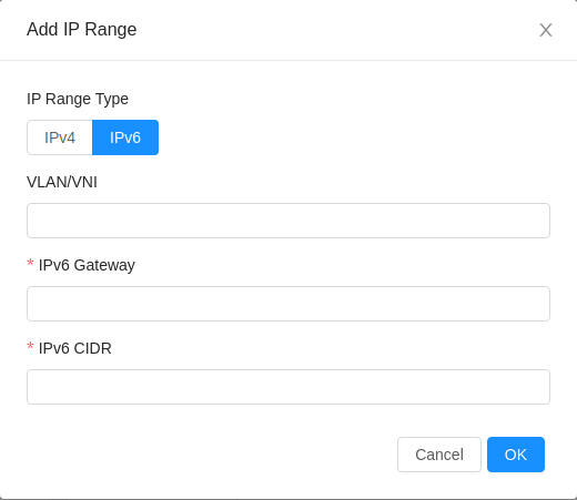
The CIDR size must be 64. Not 63, not 65, not 56. Exactly a /64.
It must be added without specifying start and end addresses, because the addresses assigned to networks are SLAAC based. CloudStack does not hand out addresses from a pool here, it derives them.
It must use the same VLAN as an existing public IPv4 range. The documentation is explicit that the public IPv6 CIDR must be added with the same VLAN as the public IPv4 range.
That third constraint is the one I want to dwell on, because it explains something that would otherwise look like a mistake in our plan. Our public IPv6 range is 2001:db8:0:40::/64 on VLAN 40, the same VLAN carrying 203.0.113.0/24. If you were designing from first principles you might reasonably give IPv6 its own VLAN for clean separation.
CloudStack will not let you, and the reason is sound once you see it: the Virtual Router's public interface is one interface. It sits in one VLAN. Dual stack means both protocols on that one interface. Separate VLANs would require a second public interface per VR purely for IPv6, doubling the interface count for no functional gain.
So the constraint is not arbitrary. It falls out of the VR's three interface architecture from section 6, and once you connect those two facts it stops being a rule to remember and becomes a consequence you can derive.
Clause two: the guest IPv6 prefix must be shorter than a /64, and its size is a product ceiling
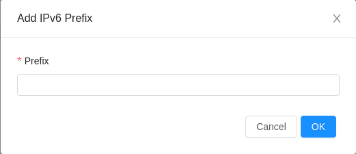
The rule: the CIDR size for the guest IPv6 prefix must be less than 64, and CloudStack carves exactly one /64 per guest network out of it.
Which means the prefix length you choose is the cap on dual stack guest networks in that zone. Count the /64 blocks and you have counted your product ceiling.
| Guest prefix | /64 networks available | Verdict |
|---|---|---|
/56 | 256 | Looks sufficient. Is a renumbering project waiting for customer 257 |
/48 | 65,536 | Our choice. Beyond any plausible ceiling |
/32 | 4.29 billion | Absurd, and also our entire LIR allocation. Do not spend all of it on one zone |
The /56 is the trap, and it is a trap specifically because 256 sounds like plenty. It is the number a careful engineer picks when applying IPv4 instincts to IPv6: big enough with room to spare, tidy, not wasteful. And it caps the zone at 256 dual stack networks, which a growing hosting provider reaches.
A /48 per zone out of our /32 costs us 1 of 65,536 available /48 blocks. Doc 2 said it and it bears repeating: being stingy in IPv6 creates work rather than saving anything.
2001:db8:1::/48.Clause three: no IPv6 only networks, which forces IPv4 planning regardless
The documentation is unambiguous on this: currently a guest network cannot be IPv6 only. It can only be IPv4 only or dual stack. The same applies to shared networks, where the docs state that a shared network cannot be IPv6 only and therefore you must configure an IPv4 range for the shared network with IPv6 addresses.
Sit with how much this constrains the strategy, because it undercuts a plan that sounds very attractive on paper. The obvious answer to IPv4 scarcity is to sell IPv6 only instances at a lower price and let the market move. CloudStack will not let you build that product. Every single guest network needs IPv4 addressing, so IPv4 planning is mandatory no matter how IPv6 first your thinking is.
What saves the plan is the distinction between private and public IPv4. The mandatory IPv4 is guest network addressing, which comes from RFC 1918 space, and there is plenty of that. What stays scarce is public IPv4 for source NAT and static NAT. So the product shape that works is: private IPv4 always, public IPv6 generously, and public IPv4 as a metered, priced resource.
That is exactly the conclusion Doc 2 reached from a completely different direction, which is a reassuring sign that both analyses are right.
The static routing reality, and the escape hatch
Here is the operational catch that will shape your automation. The documentation states that IPv6 isolated networks and VPC network tiers only support static routing, which means the administrator must add upstream routes for routing to work inside the networks.
Read the consequence at production scale: every time a customer creates a dual stack network, somebody or something must add a route in the upstream router. If that is a person, then customer self service for IPv6 does not exist, because provisioning waits on a human.
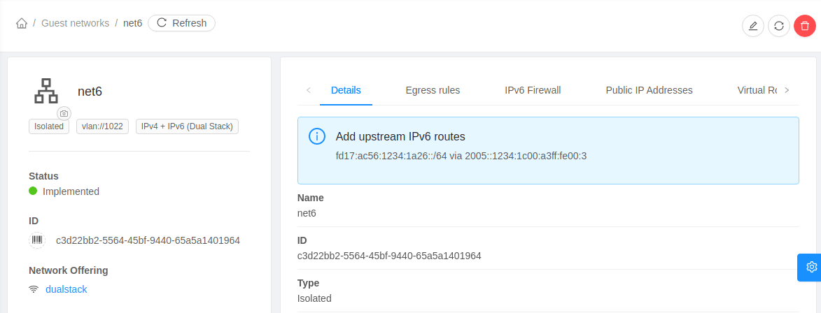
The good news is that CloudStack gives you everything needed to automate this rather than leaving you to poll.
Events. CloudStack Event Notification generates events on network creation and deletion, and on assigning or releasing a public IPv6 address for a network. So you get a trigger rather than having to discover the change.
API fields. The listNetworks response returns the gateway and subnet that the network needs configured upstream. So you get the parameters, not just the notification.
UI visibility. The required routes appear in the network details view, exactly as in the screenshot, which is how a human verifies what the automation did.
Put those three together and the pattern is clear: a listener on the event stream calls listNetworks for the affected network, extracts the prefix and next hop, and pushes a route to the upstream router through whatever configuration management owns it. That is a small, well defined piece of automation, and it is mandatory rather than optional, because without it IPv6 provisioning is a manual ticket.
It also belongs in Volume 4, alongside the GitOps pipeline, and I am naming it here so it arrives on that backlog as a known requirement rather than as a surprise during the first IPv6 customer onboarding.
There is a better answer, and it is the bridge into section 10. Dynamic routing mode removes the manual route addition step, because the Virtual Router announces its prefixes over BGP and the upstream learns them automatically.
The tradeoff: you now run BGP sessions with customer Virtual Routers, which means operator registered AS number ranges, registered BGP peers per zone, and a meaningfully more sophisticated network. Section 10 covers exactly what that entails.
Which reframes the automation task above in a way I find clarifying: the event listener is a bridge, not a destination. It gets IPv6 into production with static routing while dynamic routing is evaluated properly, and it becomes unnecessary the day dynamic routing is enabled. Knowing a piece of automation has an expiry date changes how much effort you should invest in it.
Feature maturity, stated honestly
The documentation is candid, and repeating that candour is the responsible thing to do.
Shared network IPv6 is described as an experimental feature, supported only on KVM and XenServer. And within it, three things are explicitly not yet supported: security groups, user data and metadata, and passwords.
Isolated network and VPC IPv6 is a firmer feature, available since 4.17, with the static routing caveat above.
So here is what we promise, and it is written this way deliberately:Dual stack on isolated networks and VPCs: a supported product feature, with an SLA.
IPv6 on shared networks: not offered in the initial product. Not because it does not work, but because security groups are the only isolation mechanism a shared network has, and if security groups do not apply to IPv6 traffic then IPv6 on a shared network is an unfiltered network. That is not a maturity concern, it is a security hole with a feature name.
IPv6 only instances: not offered, because the platform does not support it.
Writing the limitations into the product description is not weakness. It is what makes the rest of the description trustworthy, which is the whole argument of the trust posture document.
How this reconciles with Doc 2
| Doc 2 said | CloudStack requires | Reconciled value |
|---|---|---|
A /32 LIR allocation | Nothing specific at this level | 2001:db8::/32 |
A /48 per customer | One /64 per guest network, from the zone guest prefix | Adjusted. See the note below |
A /64 per network | Exactly this. CloudStack carves /64 per network | Aligned with no change |
A separate /48 for infrastructure | Nothing. CloudStack does not manage it | 2001:db8:0::/48, with 2001:db8:0:40::/64 as the zone public range |
Doc 2 proposed a /48 per customer, which is the registry default for an end site and a genuinely good plan.
CloudStack's model does not express it. The guest IPv6 prefix is a zone level setting, and CloudStack carves /64 blocks from it per network, not per account. There is no layer in between where a customer's /48 could live. A customer with three networks gets three /64 blocks, and there is no guarantee they are adjacent or aggregatable.
What survives, and it is the part that mattered: every customer network gets a full /64, which is 18 quintillion addresses, which is more than any customer will use. The generosity survives. The aggregation does not.
The honest correction, since Doc 2 is now partly wrong and I would rather say so than quietly leave it: the per customer /48 is the right model for a network you build yourself and for delegating to a customer who runs their own routing. It is not what CloudStack's isolated network model produces, and no configuration makes it produce that. If per customer aggregation becomes a real requirement, for example because a customer wants to announce their own space, the answer is a routed mode network with a registered subnet, which is section 10, not a different guest prefix setting.
10. NATTED versus ROUTED, and BGP from the Virtual Router
The analogy: the hotel front desk versus the private street address
NATTED mode is the hotel. Guests share the building's street address, the front desk translates between the outside world and room numbers, and a guest who wants to receive a delivery arranges it with the desk in advance. That arrangement is a port forwarding rule.
ROUTED mode is a private house on its own street address. Post arrives directly. No desk, no translation, no arrangement needed, and no front desk services either.
From CloudStack 4.20.0.0, isolated networks and VPCs can be created in ROUTED mode alongside the traditional NATTED mode.
NATTED is the default. The Virtual Router provides Source NAT, plus Static NAT, Load Balancer, Port Forwarding and VPN if the network offering supports them.
ROUTED means guest subnets are routed natively. The VR no longer supports Source NAT, Static NAT, Load Balancer, Port Forwarding or VPN. What remains is DNS, DHCP, user data, and Firewall for isolated networks, or Network ACL for VPCs and VPC tiers.
What each mode gives and takes
| Service on the Virtual Router | NATTED | ROUTED |
|---|---|---|
| Source NAT | Yes | No |
| Static NAT | Yes | No |
| Port forwarding | Yes | No |
| Load balancer | Yes | No |
| VPN | Yes | No |
| DNS | Yes | Yes |
| DHCP | Yes | Yes |
| User data | Yes | Yes |
| Firewall, or Network ACL for VPC | Yes | Yes |
Read the No column as a product feature list you are deleting. Load balancing and VPN are things customers pay for. Port forwarding is how a customer exposes a service on a shared address. Removing all five is not a technical simplification, it is a change to what you sell.
Zone level IPv4 subnet registration for routed networks
Routed networks need real, routable subnets, so the operator has to register the space first. This mirrors the IPv6 prefix model exactly, and the documentation makes the comparison itself: like IPv6 prefixes, operators need to configure the IPv4 subnets for the zone, which will eventually be used by guest networks.
The hierarchy: the operator registers IPv4 subnets for the zone. Individual guest network subnets are carved from that parent, within configured size bounds. When a user creates a routed network they specify a CIDR size rather than a CIDR, and CloudStack allocates a block of that size.
There is an account level setting, routed.ipv4.network.cidr.auto.allocation.enabled, which when true lets CloudStack allocate a subnet automatically from the zone subnets the account can access, rather than requiring the user to name one.
Dynamic routing: BGP from the customer's Virtual Router
This is where Doc 2 stops being theory.
AS number ranges, per zone. Registered under Infrastructure, then Zones, then the zone, then AS Number. Each dynamic routing network is allocated an AS number from this pool automatically.
BGP peers, per zone. Registered in advance. Guest networks with dynamic routing connect to all BGP peers the account can access.
Then the network offering with routing mode set to Dynamic. From the user's point of view the creation steps are almost identical to static routing, and the only difference is which offering they pick.
Which peers a given network talks to depends on ownership and one setting. If the network owner has no dedicated BGP peers, or the account setting use.system.bgp.peers is true, the VR peers with all BGP peers the owner can access. If the owner has dedicated peers and use.system.bgp.peers is false, the VR peers only with the dedicated peers of that domain and account.
This is the kind of behaviour that turns a routine change into a customer visible incident, so it belongs in a runbook rather than in somebody's memory.
If you update a BGP peer or the network settings, existing Virtual Routers are not reconfigured. A network or VPC restart is required for the change to take effect.
Now think about what that means at scale, because this is the part that reframed it for me. You change your upstream peer's address, perhaps because your transit provider renumbers your link. Every customer network using dynamic routing keeps its old configuration. Fixing it means restarting every affected customer network, and each restart is a brief interruption for that customer.
So a single upstream change becomes a scheduled maintenance affecting every dynamic routing customer. That is a real operational cost, and it needs to be understood before you sell dynamic routing to a hundred customers, not after.
Which is a decent argument for keeping the upstream peer set small and stable, and for treating BGP peer configuration as an infrequent, planned change with a communication plan attached.
The product decision, and why the answer is a hybrid
Decision: the default product is a NATTED isolated network, dual stack, with static IPv6 routing at launch and event driven automation to push upstream routes. ROUTED mode is a premium tier, not the default. Dynamic routing is a phase two evaluation.
Why NATTED for IPv4, and it is the same argument as section 2: we have a /24 to a /22. Routed mode consumes real public IPv4 per customer subnet, so a /24 divided into /28 customer blocks serves 16 customers. NATTED with one source NAT address per network serves hundreds. The counting decides it, exactly as it did for basic versus advanced.
Why dual stack rather than IPv4 only: IPv6 is where the address generosity lives, and section 9 established that IPv6 only is not available, so dual stack is the most IPv6 forward product the platform can express.
Why ROUTED as a premium tier rather than not at all: some customers genuinely want a routed subnet with no NAT in the path, and they are willing to pay for the public space it consumes. Price it at the real cost of the addresses and it becomes a good product rather than an inventory leak. Note that these customers also lose load balancing and VPN from the VR, which they must be told clearly, and which they usually do not mind because they run their own edge.
Why dynamic routing is phase two: it removes the static route automation entirely, which is genuinely attractive. It also brings the peer change restart problem above, per host and per network BGP state, and a real dependency on our own BGP maturity from Doc 2. Sequence it after the platform is stable and after we have operated our own BGP sessions for a while.
The common industry compromise, and it is what our default lands on: NAT for IPv4 because it is scarce, routed for IPv6 because it is abundant. Customers get a native, unNATed IPv6 address on every instance and a NATed IPv4 path, which is the correct shape of the internet in 2026 and quietly pushes the ecosystem in the right direction.
11. Pitfalls, ranked by how often they bite
I have ordered these by frequency rather than by severity, because the thing most likely to cost you a day is not the thing most likely to end your career. Read them in this order and you will debug in the right order too.
The community troubleshooting guidance says it plainly: in the vast majority of cases the problem turns out to be the switching layer configured incorrectly.
What this means for your first hour of debugging: before you read a CloudStack log, before you restart an agent, before you post a question anywhere, prove that the VLAN you care about actually traverses the trunk between two hosts.
The test is in Doc 3 and it is worth repeating the shape of it here:
- Create a tagged interface on the VLAN in question, on two hosts
- Give each a temporary address in a throwaway subnet
- Ping between them
- Capture with
tcpdump -eand confirm the frames actually carry the tag you expect
Step four is the one people skip and it is the only step that proves anything. A successful ping can happen for the wrong reason, most commonly because the traffic is landing in a different VLAN than you believe. The capture is what distinguishes "it works" from "it works the way I designed it".
The mental discipline: CloudStack is a plausible suspect and the switch is the likely culprit. Investigate in order of likelihood, not in order of which component you find more interesting.
Labs and deliverables
| Deliverable | What it must contain |
|---|---|
| Traffic type mapping sheet | Each CloudStack traffic type mapped to VLAN, subnet, bridge, host NIC, and label. Section 1 |
| Zone IP plan | Pod reserved system range, public ranges, guest CIDR scheme, storage range, all sized with the arithmetic shown. Section 5 |
| Bridge build runbook | Exact host interface and bridge configuration, identical across every host in the cluster, generated from one source of truth. Section 3 |
| Port and firewall matrix | Source zone, destination, port, direction, purpose, and the rule that implements it. Section 7 |
| Pre install verification checklist | Trunk test, MTU test, storage subnet test, OOB test, DNS and NTP reachability. The gate below |
| Isolation method decision record | VLAN now, VXLAN triggers, with the counting that justifies the threshold. D1-05-02 |
| Network mode decision record | NATTED, ROUTED, or hybrid, with product and address consequences stated. D1-05-03 |
| IPv6 route automation specification | Event listener, listNetworks query, upstream push mechanism, and its expiry condition. Section 9 |
Everything else here can be rebuilt from the official documentation with enough patience. The decision records cannot, because they contain the reasoning, the counting, and the trigger conditions that are specific to our business.
A decision record with a trigger condition is the difference between a design and a plan. "We chose VLAN" is a design. "We chose VLAN, here is the counting, and at 600 of 900 guest networks we start the VXLAN project" is a plan, and it survives the person who wrote it leaving.
The verification gate before Volume 4
Every item above is something CloudStack silently assumes. Not validates, not warns about, not reports. Assumes.
Checking them as a gate turns a week of confusing platform debugging into an afternoon of network verification. This is the same discipline as the quality gates in SSDLC: fail closed, fail early, fail cheaply.
Notice the dotted failure arrows on four of the steps, because they are the point of drawing this as a diagram at all. Those four are the ones where continuing anyway is genuinely worse than stopping. A failed trunk test, a wrong storage route, an exposed 8250, or an untested failover are each capable of consuming more time later than the entire verification takes now. The gate is not bureaucracy. It is the cheapest hour in the project.
Success criteria
You are done with this doc when you can do all of the following without looking anything up:
- Name all four traffic types and state which one does not carry primary storage traffic, and explain why
- Point at each hypervisor bridge and say which traffic type and VLAN it serves, and which one has no IP address and why that is correct
- Explain why the public VLAN must be trunked to every host even though an external firewall is the gateway
- Produce the pod reserved system IP range and justify its size with arithmetic, not with a round number
- List every port that must never be reachable from the internet, and name the one that needs no credentials at all
- Explain why the console proxy VM turns a multi pod zone into a single routable management domain
- State the three mandatory constraints on a public IPv6 range and the one that caps your dual stack network count
- Defend your VLAN versus VXLAN choice with counting, and your NATTED versus ROUTED choice with product reasoning
- Describe what a successful firewall flush on a system VM actually tells you
Hand this document's IP plan tables to somebody who was not in any of these conversations, and ask them to build the zone.
If they can do it without asking you a question, the document works. If they have to ask, the answer they needed belongs in here, and the gap is worth fixing while it is cheap. That is the actual standard for infrastructure documentation, and it is a much higher bar than "it is accurate".
Attribution
The CloudStack interface screenshots and architecture diagrams in this document come from the Apache CloudStack documentation, licensed under the Apache License 2.0. The VLAN tag, VXLAN header, VXLAN tunnel and VXLAN multicast diagrams come from Wikimedia Commons under CC BY-SA. Every technical claim is checked against the official documentation for the current release, and where behaviour has changed between versions or where the documentation is candid about a feature being experimental, I have said so in place rather than smoothing it over.
Volume 1 complete. Next stop: Volume 2, the lab environment, where every plan in this document gets built as a simulated datacenter on a laptop and the design finally has to survive contact with a real hypervisor. Then Volume 4, CloudStack platform where it gets built for real.