Projects · Mini Hostpapa
Datacenter & Physical Network Foundations
Colocation, racks, power, cabling, top of rack switching, VLAN trunking, bonding, MTU, and out of band management, with photographs of the actual hardware.
Datacenter & Physical Network Foundations
Okay. Docs 1 and 2 were about concepts and identity. Packets, addresses, routing, who owns what.
This one is about metal, copper, fiber, watts, and rack units. It is the part where a mistake costs a drive to the datacenter instead of a config reload.
You get one clean install window.
Cables you label badly today, you re trace at 3 in the morning next year with a flashlight held in your teeth. Physical discipline is not aesthetics and it is not perfectionism. It is mean time to repair, and mean time to repair is the number your customers actually experience during an incident.
Volume 0 already showed you the rack at executive level: one 42U cabinet in a Tier III or IV class facility in Tunisia, an edge firewall, a top of rack switch, a small out of band switch, two CloudStack management servers, three or four KVM hosts, and one NFS storage node. That page deliberately said "VLAN IDs come later."
Later is now. Here we turn that sketch into something you could hand to a colo engineer and a hardware vendor without flinching.
I have walked datacenter floors, and the honest truth is that reading about this hardware is nothing like seeing it. So every section here shows you the actual metal, with photographs, and tells you what to look at in each one.
If you have never racked a server, the goal is that by the end of this page you can recognize every component, name it, and explain what it is for. That is most of the gap between someone who has done it and someone who has only read about it.
The two things that surprised me most on a datacenter floor, and nobody writes them down: it is genuinely cold, cold enough that you want a jacket in July, and it is loud, loud enough that you have to raise your voice to be heard next to a rack. Both of those are engineering choices you are about to learn the reasons for.
What you will be able to produce after this document
| Output | Who consumes it |
|---|---|
| Rack elevation diagram with U positions and weight distribution | Colo provider, install technician |
| Power budget in kW with A and B feed split | Colo contract, finance |
| Port map and cabling schedule with labels | Remote hands, and future you |
| VLAN table with IDs, subnets, gateways, and purpose | Doc 4, Doc 5, and Volume 5 |
| Switch and firewall hardware requirements list | Procurement |
| Out of band access plan | Security review, on call runbooks |
1. Colocation, decoded
The analogy: renting a serviced office
You do not build your own office tower to run a ten person company. You rent a unit in a building where somebody else handles the power, the air conditioning, the lifts, the security desk, and the fire suppression.
You bring the desks, the computers, and the locks on your own door. And when you need something moved while you are away, you pay the building concierge by the hour.
Colocation is exactly that, for servers. The provider runs the building. You own everything inside your cabinet, and you own every decision about what crosses your cabinet boundary.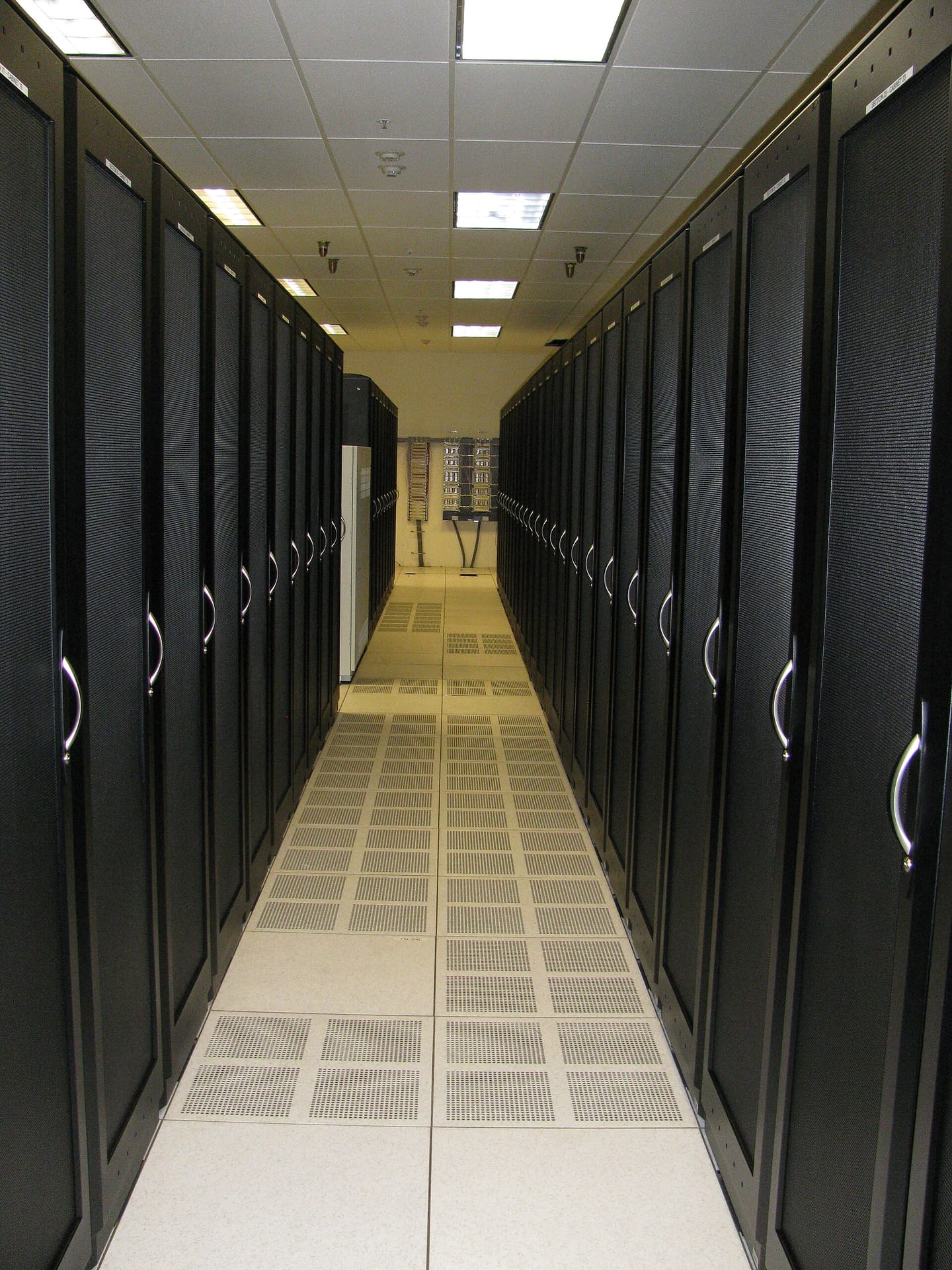
Study that photo for a second, because it contains most of section 2 already. The doors are mesh, not solid, so air can pass through. The floor is raised, with removable tiles. And the tiles in the walkway are perforated, while the tiles under the cabinets are solid.
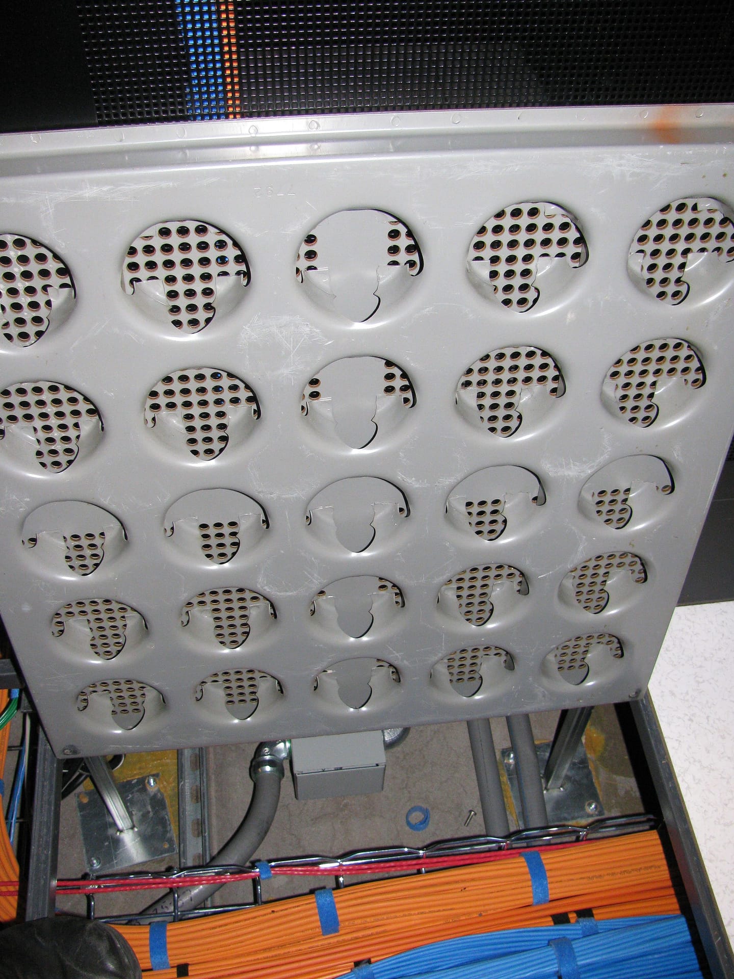
This is the design that made the "it is genuinely cold in there" observation click for me.
Chilled air is pumped into the void under the raised floor, rises through the perforated tiles into the aisle, gets sucked in through the front of every server, absorbs heat from the components, and is blown out the back into the other aisle.
So a datacenter has cold aisles, where server fronts face each other and you stand, and hot aisles, where server backs face each other. Walk from one to the other and the temperature difference is dramatic and immediate. All servers in a row must face the same way, or you get a server inhaling its neighbour's exhaust, which is exactly as bad as it sounds.
What colo actually sells you
| What you buy | What it means in practice | What to check in the contract |
|---|---|---|
| Space | A cabinet, a locked cabinet, a cage, or a private room | Cabinet height in U, and depth in mm, because deep servers do not fit shallow cabinets |
| Power | A committed number of kilowatts per cabinet, on one or two feeds | kW per rack, whether it is A and B redundant, and what happens if you exceed it |
| Cooling | Keeping the cold aisle at a target temperature | Whether your power density is actually coolable in that row |
| Physical security | Access control, cameras, escorts, logging | Who can open your cabinet, and whether that is logged |
| Cross connects | A physical cable from your cabinet to a carrier or an exchange | Price per cross connect, and the lead time to install one |
| Remote hands | Their technician physically touching your gear on your instruction | Hourly rate, minimum billing increment, and response time commitment |
The bits of the building you will never own, but must understand
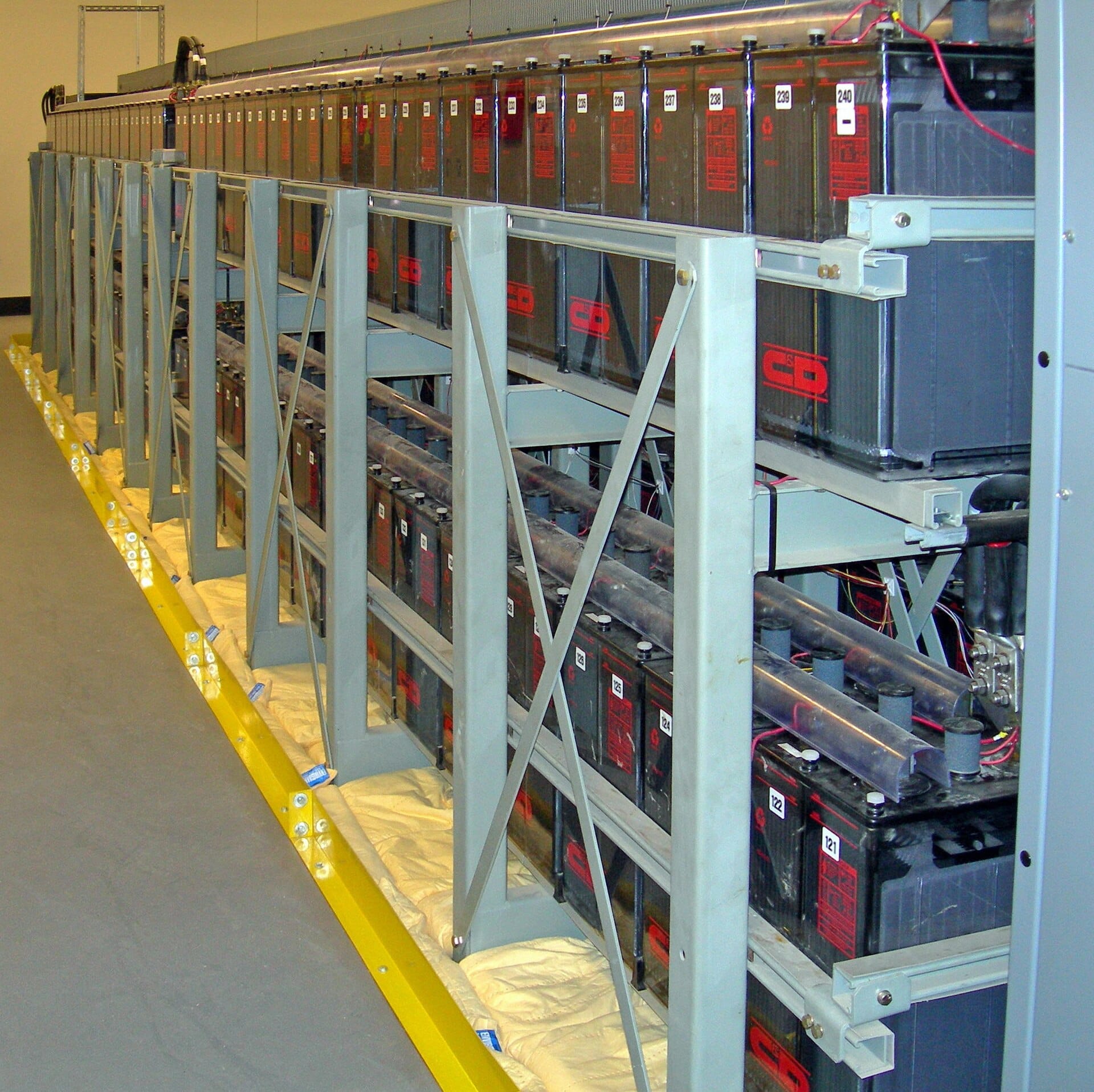
Here is the chain of events on a utility power failure, and understanding it is what lets you read a Tier claim honestly: utility power dies, and the UPS batteries take the load instantly, because there is no time to wait for anything mechanical. The generators start and take perhaps thirty seconds to a minute to stabilize. Once they are stable, the load transfers to generators, and the batteries recharge. The batteries are not there to run the building for hours. They exist to cover the gap until the generators are ready.
Tier is an industry classification for how redundant the power and cooling are. Higher is stricter. You do not need to memorize the standard, and a provider saying "Tier IV" on a brochure is marketing until you read the contract.
What actually matters, and what you should ask on the tour:
Are the two power feeds genuinely independent all the way back, or do they merge somewhere upstream? A single point of failure hidden three floors down is still a single point of failure.
How often are the generators load tested, and can you see the records? A generator that has never been tested under load is a decoration.
Is cooling redundant, and what is the actual failure behaviour? Losing cooling gives you minutes, not hours.
How many carriers are in the building, and can you reach more than one? This is the physical prerequisite for the multihoming discussed in Doc 2. No second carrier in the building means no ASN qualification, no matter what you want.
The meet me room and cross connects
The meet me room is the space in a colocation facility where all the carriers terminate their networks. It is the marketplace of the building.
A cross connect is a physical cable run from your cabinet to somebody else's equipment in that room, usually installed by the provider's technicians and billed monthly.
Why this matters commercially: the number of carriers in the meet me room is the number of transit providers you can realistically reach without expensive external circuits. A building with one carrier is a building where you can never be multihomed. Ask this question before you sign, not after.
The questions to read aloud on the tour
Print these. Genuinely.
| Question | What a bad answer sounds like |
|---|---|
| How many kW per cabinet, and is that per feed or total? | Vagueness. This number must be exact, because your budget in section 3 depends on it. |
| Are A and B feeds independent to the building entrance? | "They are both redundant" without explaining the path |
| Which carriers are in the meet me room today? | A list of who they are "in discussions with" |
| What is the cross connect fee and lead time? | No published price |
| What is the remote hands rate and response commitment? | Best effort with no number attached |
| Who can physically open my cabinet, and is it logged? | Anything other than a specific, auditable answer |
| Can I see generator test records? | Hesitation |
| What is the cabinet depth in millimetres? | "Standard." There is no standard depth. |
That last one sounds trivial and it is the question that saves an install day. This ties directly into the physical controls we committed to in governance, risk and compliance, where physical security is an audited control rather than an assumption about somebody else's building.
2. The rack as an engineering artifact
The analogy: a bookshelf with standardized slots
A rack is a metal bookshelf where every shelf position is a standard height, so any manufacturer's equipment fits any rack. That standardization is the entire reason a hardware ecosystem exists.
The slot is called a rack unit, written U.
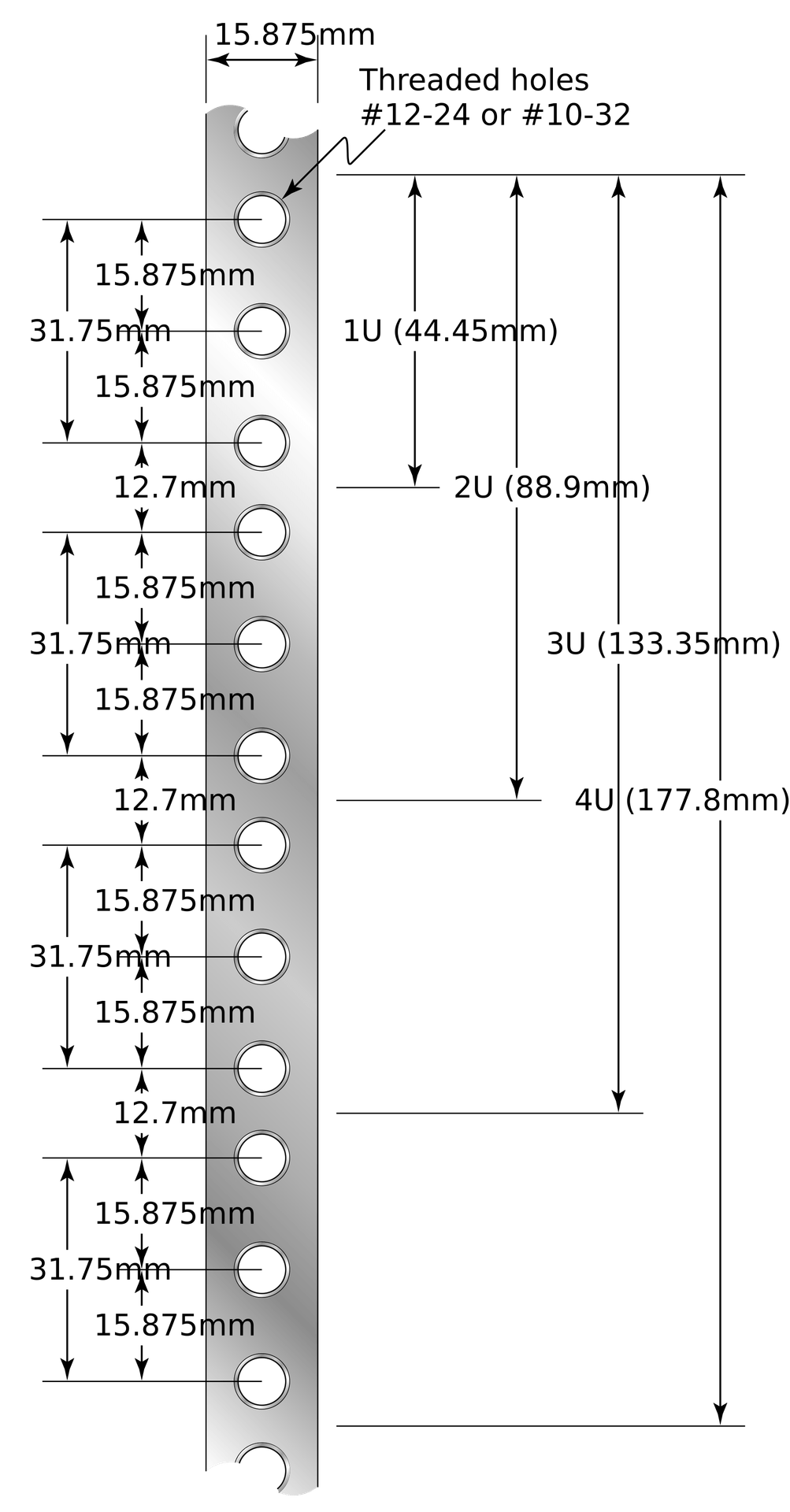
At first I found the 1U measurement genuinely strange, and here is the trick to understanding it: 44.45 mm looks like a random number until you realize it is exactly 1.75 inches. The whole standard is imperial, defined decades ago, and the metric numbers are just conversions. That is why nothing about it is round.
Now look more carefully at that drawing, because it contains a detail that trips up every first timer. Each U has three mounting holes, and they are not evenly spaced. The gaps go 15.875, 15.875, then 12.7 mm before the next U begins. That uneven gap is how you can tell where one U ends and the next starts.
Because the holes are unevenly spaced, it is entirely possible to mount equipment straddling a U boundary, using the wrong three holes. Everything appears to fit. Then the next device up will not mount, because the remaining holes no longer line up with a U boundary, and you have to unrack and redo it.
Good cabinets have U numbers printed on the rails. Use them. Count from the bottom, and mount to the printed numbers rather than by eye.
Height is the easy dimension. Depth and rails are the hard ones.
| Dimension | What to know | What goes wrong |
|---|---|---|
| Width | 19 inches between rails, effectively universal | Rarely a problem |
| Height | Measured in U. A full cabinet is typically 42U or 47U. | Running out of U, which is a planning failure not a surprise |
| Depth | Varies significantly. Deep servers need roughly 1000 mm or more of cabinet depth. | The server physically does not fit, or fits with no room for cable bend radius behind it |
| Rail type | Square hole, round threaded, or tapped. Your rail kits must match. | You arrive with rail kits that do not fit the cabinet and can do nothing about it that day |
Depth is the dimension that ruins install days because everybody remembers to count U and nobody thinks to measure how deep the cabinet is. Ask for cabinet depth in millimetres and compare it against the deepest server on your purchase order, then add room behind it for cables to bend.
Weight, and why the heavy things go at the bottom
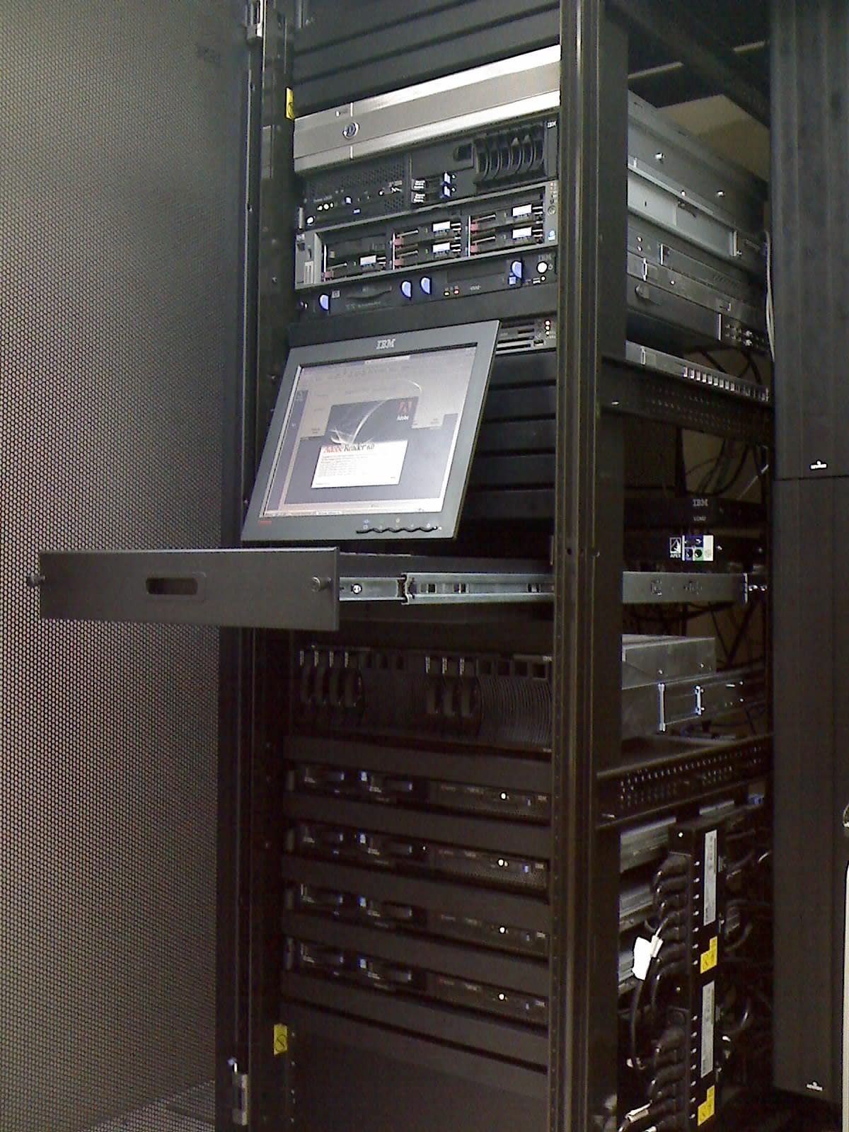
Bottom of the rack: storage and anything heavy. A fully populated storage node is genuinely heavy, and a tall cabinet with the weight at the top is a tipping hazard when you slide something out on rails. Same reason you put heavy books on the bottom shelf.
Middle: compute hosts. The bulk of the equipment, accessible without a ladder or crouching.
Top: network gear. The switch goes at the top so that every cable run from the servers below is short and travels upward, which is exactly where the name top of rack comes from.
Also consider the floor loading limit, which the colo provider publishes and which genuinely constrains dense storage builds.
Airflow discipline, and the cheapest mistake in this document
An empty U in the middle of your rack is an open hole between the cold aisle and the hot aisle.
Hot exhaust air takes the shortcut backwards through that hole into the cold aisle, where it gets inhaled by your servers. Your equipment now breathes its own hot exhaust, fans spin up, power draw rises, and component life shortens. All of it caused by a gap.
A blanking panel is a flat plate that fills an unused U and blocks that shortcut. They cost a rounding error and they are the highest return per dinar item in this entire document. Fill every unused U.
Rack elevation: the actual layout for our starter footprint
This is the artifact you hand to the install technician. It takes the Volume 0 equipment list and gives every item a specific U position.
| U position | Device | Size | Why it is there |
|---|---|---|---|
| 42 | Patch panel, copper | 1U | Top, so all cable runs terminate above the gear |
| 41 | Cable management bar | 1U | Dresses cables between panel and switch |
| 40 | Top of rack switch, tor-sw-01 | 1U | Short runs to everything below |
| 39 | Out of band switch, oob-sw-01 | 1U | Separate physical switch, isolated, section 8 |
| 38 | Cable management bar | 1U | |
| 36 to 37 | Edge firewall, fw-edge-01 | 2U | Near the switch and the uplink handoff |
| 35 | Blanking panel | 1U | Airflow separation between zones |
| 34 | cs-mgmt-01 | 1U | CloudStack management server |
| 33 | cs-mgmt-02 | 1U | The second one, for basic HA |
| 32 | Rack console tray | 1U | Slide out screen and keyboard for on site work |
| 28 to 31 | kvm-host-01 and kvm-host-02 | 2U each | Compute, in the accessible middle band |
| 24 to 27 | kvm-host-03 and kvm-host-04 | 2U each | Compute, host 04 optional at launch |
| 13 to 23 | Blanking panels | 11U | Reserved for growth, blanked today. Not left open. |
| 9 to 12 | nfs-store-01 | 4U | Heavy, so it sits low |
| 1 to 8 | Blanking panels, growth reserve | 8U | Second storage node lands here |
| Vertical, side | PDU A and PDU B | 0U | Mounted vertically in the side channels, section 3 |
Notice that the growth space is explicitly blanked rather than left open. Reserved does not mean empty. That is the difference between a plan and a hope.
Labeling, and the naming convention we commit to
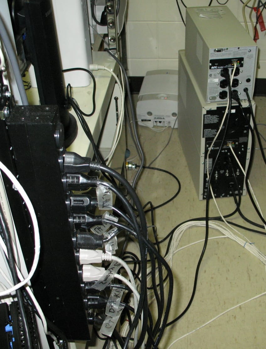
Masking tape and a marker at install time feels fine. Eighteen months later the adhesive has failed, the ink has faded, half the labels have fallen off, and the only way to identify a cable is to unplug it and see what breaks. In production. At night.
The standard we commit to:Both ends of every cable get a printed label. Both. A cable labelled at one end only is a cable you will trace by hand.
Printed, not handwritten. A label printer costs less than one hour of remote hands time.
The label says where the other end goes, not what the cable is. kvm-host-01:eth0 on the switch end and tor-sw-01:Gi1/0/5 on the host end.
Device names match CloudStack host names exactly. If the machine is kvm-host-01 in CloudStack, that is the name on the physical label, in the DNS record, in the monitoring system, and in the wiki. One name everywhere. Two names for one machine is how a 3 a.m. incident becomes an hour of confusion about which box someone means.
3. Power, the thing that actually kills uptime
The analogy: the electrical panel in your house
You know intuitively that you cannot run the kettle, the oven, and a space heater on the same circuit, because the breaker trips. You know that a breaker tripping cuts everything on that circuit, not just the thing that caused it.
A rack is that, with a much bigger breaker and much worse consequences. And the mistake people make is thinking about power only as "will it turn on", when the real question is what happens when half of it goes away.
PDUs: the power strip that is not a power strip
A PDU, power distribution unit, takes the feed the colo gives you and splits it into outlets for your equipment. They come in three grades, and the difference genuinely matters.
| Type | What it does | Verdict |
|---|---|---|
| Basic | Splits power into outlets. That is all. | Cheapest, and you are blind. You cannot answer "how much power am I actually using?" |
| Metered | Reports actual current draw, per PDU or per outlet | Buy this. It pays for itself the first time you plan a capacity change. |
| Switched | Metered, plus you can power cycle an individual outlet remotely | Worth it for the hard reboot you cannot do any other way. See section 8. |
A customer asks whether you can host a workload that needs two more compute hosts. With a basic PDU your honest answer is "I think so", based on adding up numbers printed on the back of servers, which overstate real draw significantly.
With a metered PDU you read the actual current draw, compare it against your committed kW, and answer with a number. The second answer is a business capability, not a technical nicety, and it is the same argument as the utilization metric in Doc 2. Capacity you cannot measure is capacity you cannot sell.
A and B feeds, and the mistake I want you to never make
Serious equipment has two power supplies. The colo gives you two independent feeds, called A and B. The idea is that either one can carry the load alone, so losing a feed loses nothing.
Both power supplies plugged into the same PDU.
The server has two PSUs. The rack has two feeds. Everything looks redundant on the purchase order and on the diagram. And then feed A fails, and every server dies, because both of their power supplies were on feed A.
Dual power supplies protect you from a power supply failing, not from a feed failing, unless you actually split them. PSU 1 to PDU A, PSU 2 to PDU B, on every single device. It is like having two seatbelts bolted to the same weak point: it looks like redundancy and it protects against nothing.
This is worth checking physically, by hand, on install day, and it is on the verification list in section 10.
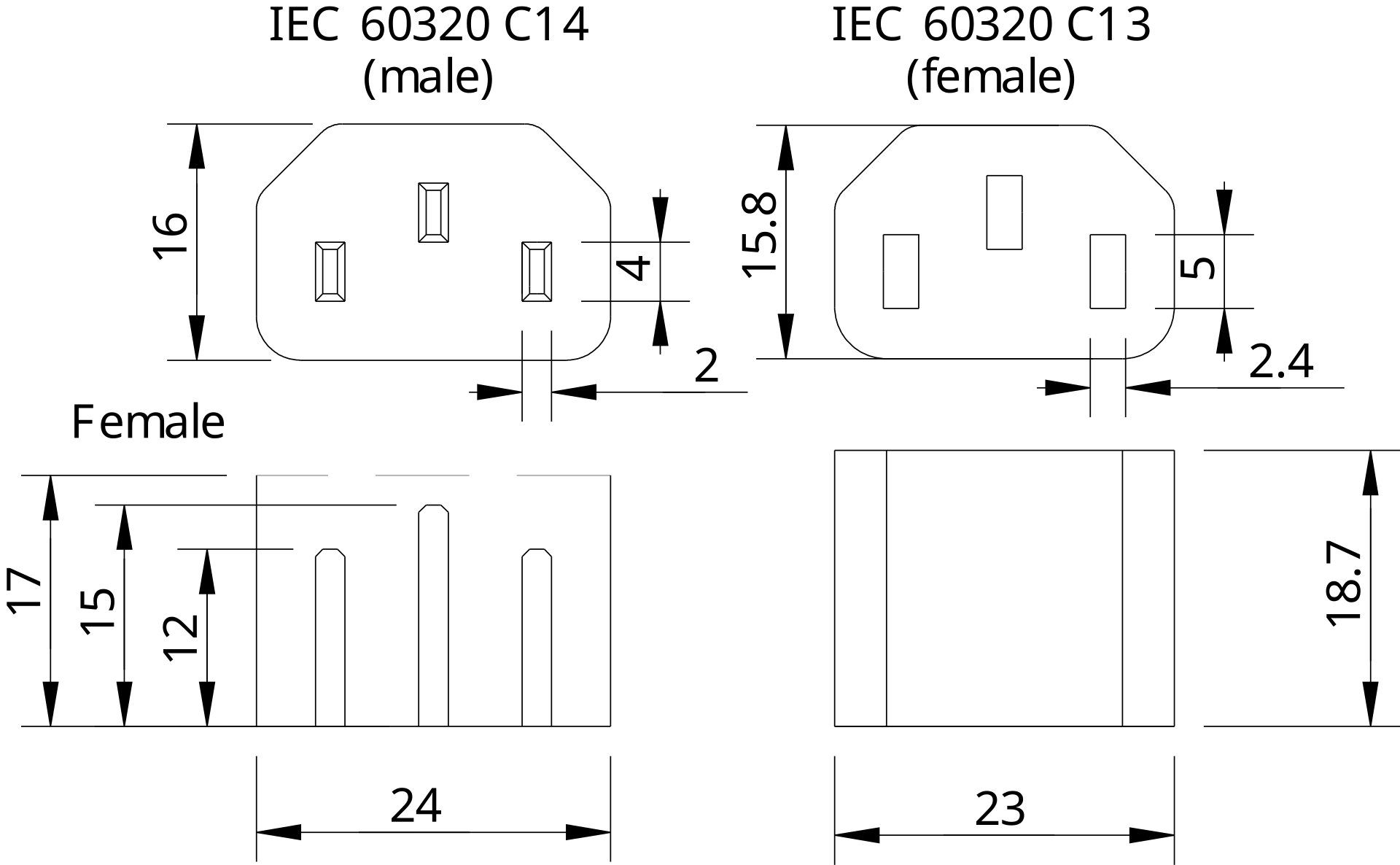
You will see these codes on every order form, and they are simpler than they look.
C13 and C14: the standard pair for most servers and switches, rated to 10 amps. The C14 is the male inlet on the device, and the C13 is the female end of the cable that plugs into it.
C19 and C20: the bigger version, rated to 16 amps, used by higher draw equipment like fully loaded storage nodes and some blade chassis.
Why you care: your PDU has a fixed number of each type. Order a PDU with only C13 outlets, buy a storage node that needs C20, and you have a box you cannot plug in. Count outlets by type, not just by quantity.
The power budget, done properly
The nameplate rating is the number printed on the power supply. It is the absolute maximum that supply can deliver, and real servers draw substantially less, often around half of nameplate under normal load.
If you budget on nameplate you will conclude you need twice the power you actually do, and pay for it monthly. If you budget on idle draw you will trip a breaker the first time everything is busy at once.
The honest method: estimate real draw under expected load, add headroom, and then measure with a metered PDU and correct your numbers once the gear is running. This is why metered PDUs are in the budget.
Here is the shape of the budget sheet, using illustrative figures you replace with vendor data and then with measurements.
| Device | Qty | Est. real draw each | Subtotal | Feed |
|---|---|---|---|---|
| Edge firewall | 1 | 100 W | 100 W | A and B |
| Top of rack switch | 1 | 150 W | 150 W | A and B |
| Out of band switch | 1 | 30 W | 30 W | A and B |
| CloudStack management servers | 2 | 150 W | 300 W | A and B |
| KVM compute hosts | 4 | 450 W | 1800 W | A and B |
| NFS storage node | 1 | 500 W | 500 W | A and B |
| Estimated total | about 2.9 kW | |||
| With 30 percent headroom | about 3.8 kW | |||
| Per feed if one fails | each feed must carry the full 2.9 kW alone |
That last row is the one people skip, and it is the whole point of the exercise. If A and B each carry half the load in normal operation, then a feed failure means the survivor carries everything. So each feed must be sized for the full load, not half of it. A pair of feeds that can each carry 50 percent is not redundant, it is a synchronized failure waiting for a trigger.
Testing a feed failure without taking customers down
Redundancy you have never tested is a belief, not a property of your system.
The safe test, run during a maintenance window while watching your monitoring:
- Confirm through the metered PDUs that both feeds are drawing current, which already catches the both PSUs on one feed mistake
- Confirm each device shows two healthy power supplies in its management interface
- Drop one feed, either by agreement with the colo or at your own PDU
- Watch for anything that powered off. That is your list of mistakes.
- Restore, wait, then repeat with the other feed
Step 4 is the entire value of the exercise. Almost every first test finds at least one device that was single fed, and finding it during a planned window is free while finding it during a real failure is an outage.
This feeds directly into capacity planning and the second rack trigger in executive metrics. Power, not rack units, is usually what runs out first. You will have empty U above a rack that has no watts left, and that is when you learn that a cabinet is sold by kilowatt, not by space.
4. Cabling and physical media
The analogy: plumbing
Copper is a garden hose. Cheap, flexible, easy to terminate, and it works fine over short distances. Push it too far and pressure drops.
Fiber is a light pipe. More expensive per end, immune to electrical interference, and it carries signal over distances copper cannot approach.
Here is the practical rule that covers ninety percent of decisions: inside the rack, use copper or DAC. Leaving the rack or the room, use fiber.
Copper: what the categories actually mean
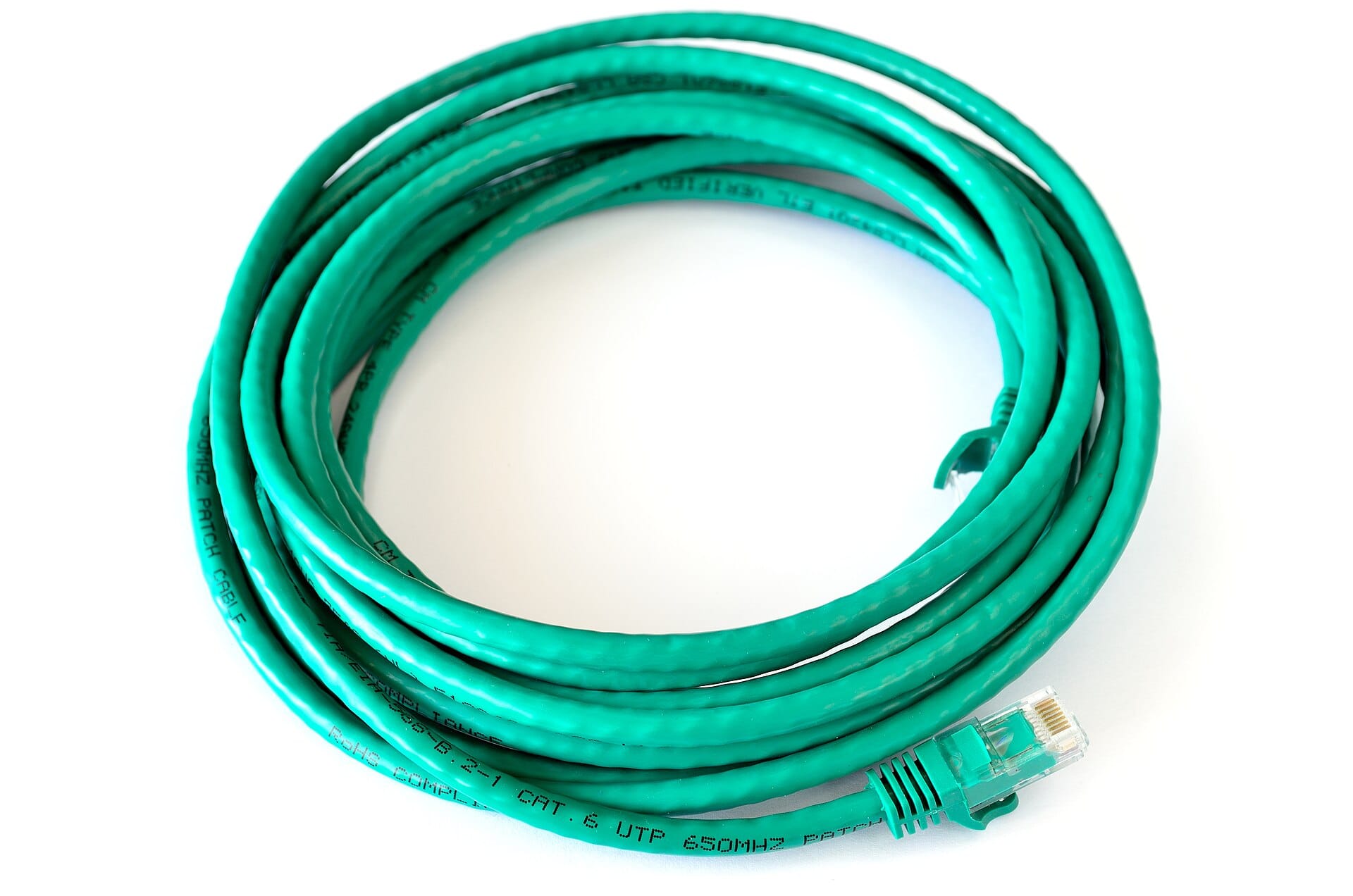
Each pair is twisted around itself, and each pair uses a different twist rate.
Electrical noise hits both wires of a twisted pair almost identically. Since the signal is carried as the difference between the two wires, identical noise on both cancels out. The differing twist rates stop adjacent pairs from interfering with each other.
That is the entire trick behind gigabit and 10 gigabit over ordinary copper. It is also why you must not untwist more than about 13 mm at the connector, and why a badly terminated cable will pass a link light test and then fail under real load.
| Category | Supports | Practical distance | Use in our rack |
|---|---|---|---|
| Cat5e | 1 Gbps | 100 m | Acceptable for out of band and IPMI only |
| Cat6 | 1 Gbps, and 10 Gbps over shorter runs | 100 m at 1G, roughly 55 m at 10G | The sensible default for management and OOB |
| Cat6a | 10 Gbps | 100 m at 10G | If you want 10G over copper structured runs |
| Cat7 and above | Higher, with caveats | Varies | Usually not worth it. Go fiber or DAC instead. |
The honest advice on copper categories: do not buy exotic copper to chase 10 gigabit. Inside a rack, DAC is cheaper, more reliable, and consumes less power than 10 gigabit over copper. Which brings us to the most useful cable in a hosting rack.
DAC: the cable that solved short 10 gigabit runs
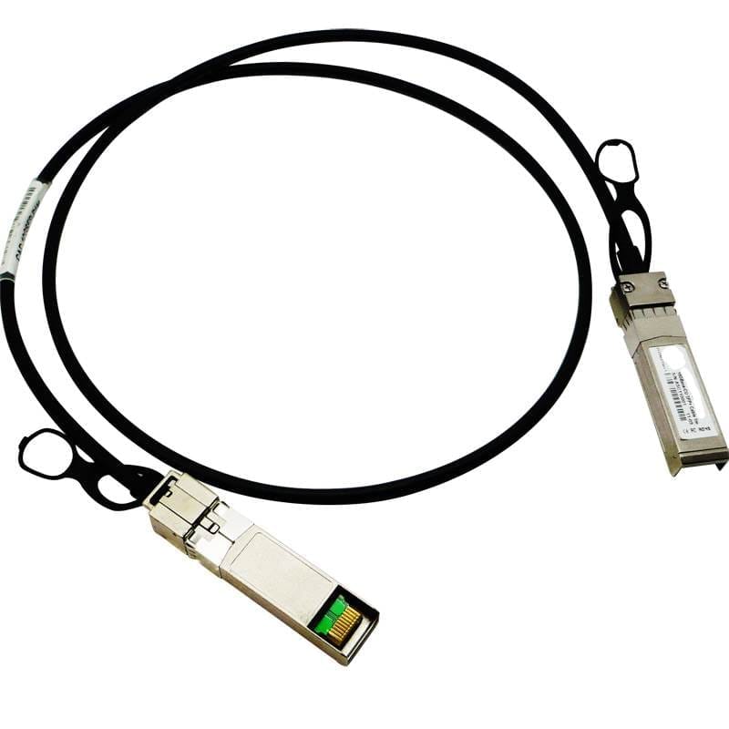
Look at the photo. Both ends are already transceivers. There is nothing to plug into anything, no optics to buy separately, no fiber end faces to keep clean.
Cheaper than two optical transceivers plus a fiber patch cable.
Lower power and lower latency, because there is no electrical to optical conversion happening at either end.
Nothing to contaminate. A dirty fiber end face causes intermittent errors that are genuinely painful to diagnose. A DAC has no end face.
The limitation: length. DAC is practical to roughly 3 to 7 metres, which is exactly the distance from any server in a cabinet to the switch at the top of that cabinet. Beyond the rack, you need optics.
Fiber and transceivers
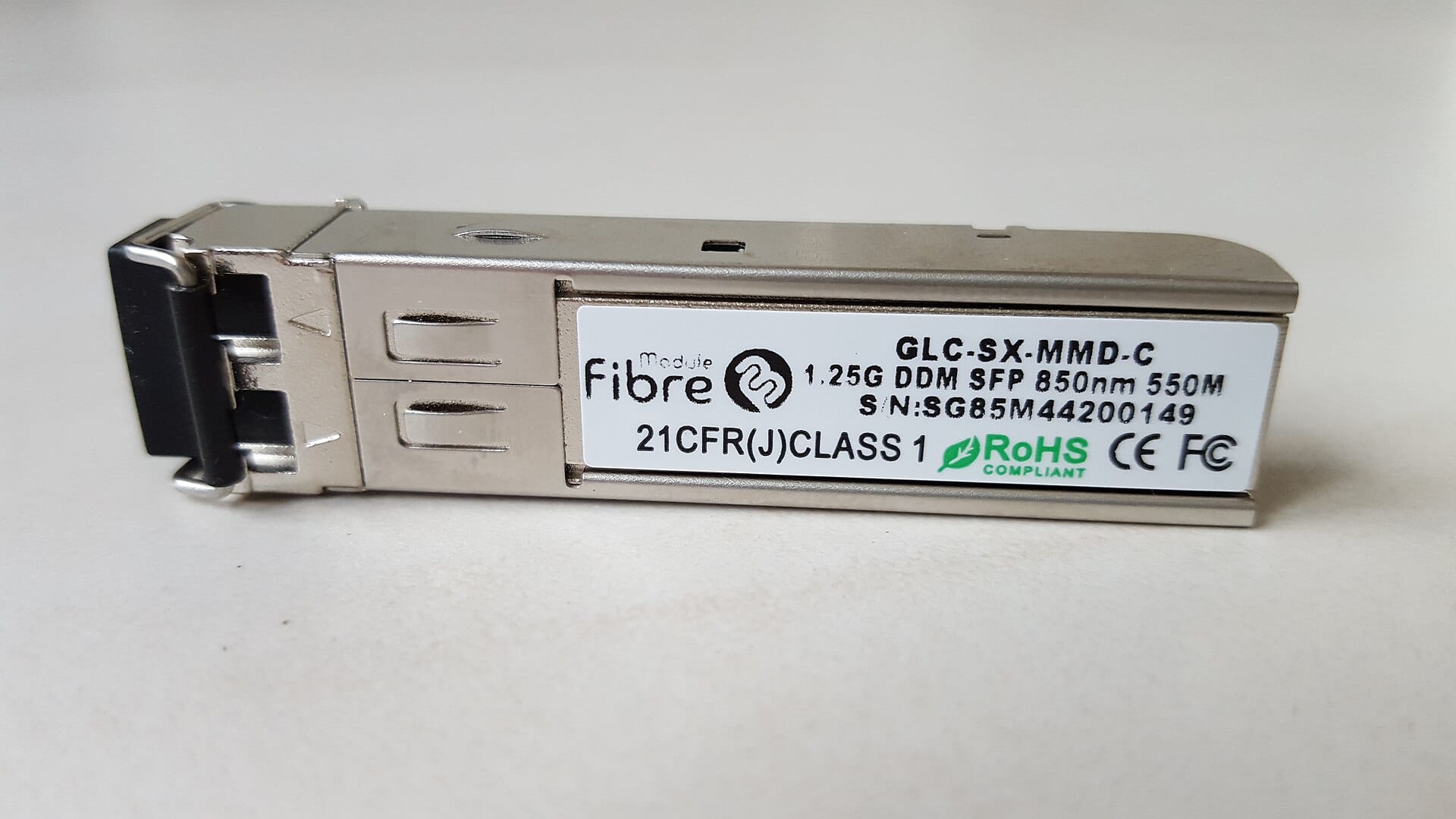
A transceiver is a removable module that converts your switch's electrical signals into light and back. The form factor names describe the physical shape and the speed.
SFP: 1 Gbps.
SFP+: 10 Gbps, same physical size as SFP. This is what our rack will use.
SFP28: 25 Gbps, still the same physical size.
QSFP+ and QSFP28: 40 and 100 Gbps, physically larger, four channels in one module.
Why the same size across speeds matters commercially: a switch with SFP+ cages can accept 1G or 10G modules in the same slot. You buy the switch once and change the optics as you grow, which is a genuinely useful property when budgeting.
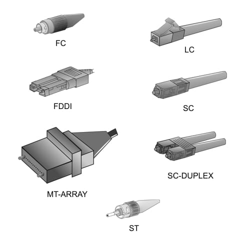
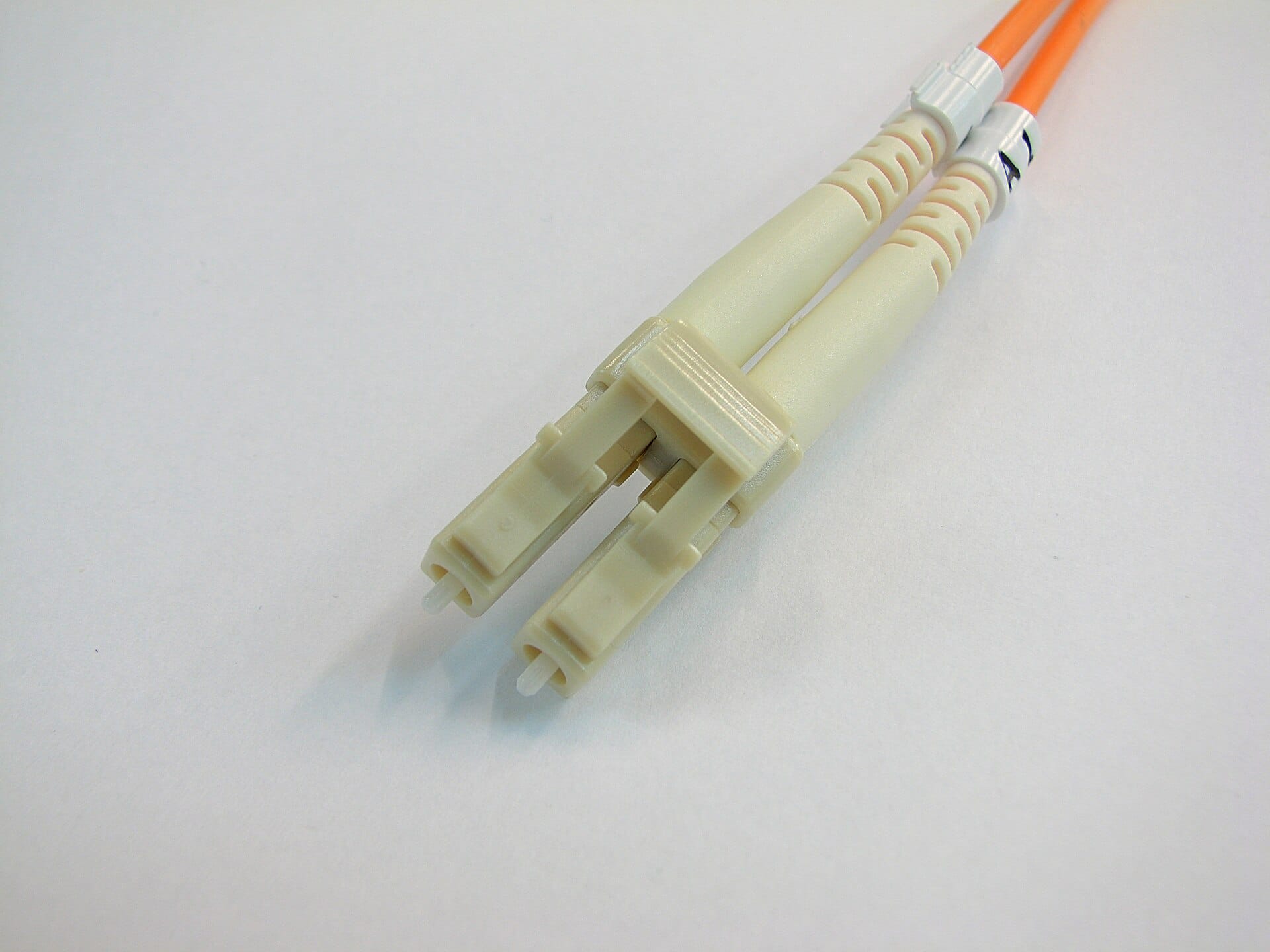
| Connector | Recognize it by | Where you meet it |
|---|---|---|
| LC | Small, with a plastic latch you squeeze | Almost everything modern. SFP and SFP+ modules use LC. |
| SC | Larger, square, push and click | Older equipment, and often the colo handoff at the patch panel |
| ST | Round with a bayonet twist | Legacy. You may inherit it. |
Multimode fibre has a wider core, uses cheaper optics, and reaches a few hundred metres. Jackets are traditionally orange or aqua.
Single mode fibre has a very narrow core, uses more expensive optics, and reaches kilometres. Jackets are traditionally yellow.
The transceiver and the fibre must match. A single mode optic on multimode fibre may produce a link that appears to work and then throws errors under load, which is a genuinely miserable thing to chase. Match them deliberately, and ask the colo which type their handoff is on before you order optics, because guessing costs you a shipping lead time.
Patch panels, and when they earn their rack unit
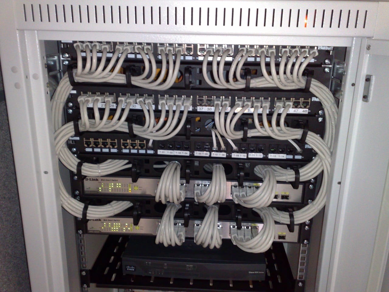
Spend a moment on that photograph, because it is the target you are aiming for. Notice that every cable is the same length, they all follow the same path, and the loops are uniform. That is not vanity. It means you can trace any single cable with your eyes, and you can remove one without disturbing its neighbours.
A patch panel is a row of ports where permanent cable runs terminate. You then use short patch cables to connect a panel port to a switch port.
Why bother, instead of running the long cable straight into the switch? Because of the wall socket principle. You do not run electrical wire from the street directly into your lamp. You terminate it at a socket, then use a short flexible cord.
The permanent run gets terminated once and never touched again. All the plugging and unplugging happens on cheap, replaceable patch cables. Replacing a switch becomes moving patch cables rather than re terminating structured cabling.
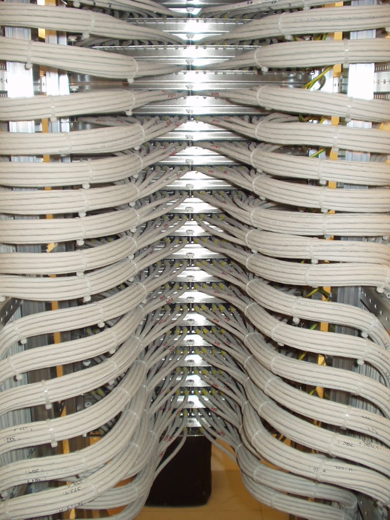
Every cable has a minimum bend radius, and violating it is how you create faults that appear months later.
For copper, a sharp bend distorts the twisted pair geometry and degrades performance at high frequencies. The cable still links, and it starts producing errors under load.
For fibre, bending too tightly causes light to escape the core. This is called macrobending loss, and it produces exactly the kind of intermittent, load dependent fault that takes days to find.
The practical rule: never pull a cable tight around a corner, never over tighten a cable tie to the point of deforming the jacket, and always leave a service loop, meaning a little slack, at each end. Look at the service loops in the two photos above. They are there on purpose.
Spare capacity, and the boring discipline that saves a growth day
| Item | How much spare to hold | Why |
|---|---|---|
| Switch ports | At least 25 percent free after install | Adding a host should never require a switch purchase |
| Patch cables, each length | A few of each | You will damage one, and shipping takes days |
| Transceivers | One spare per type in use | Optics do fail, and matching the exact type matters |
| DAC cables | One or two spare | Cheap insurance |
| Blanking panels | More than you think | Every device you remove leaves a hole that must be filled |
The reasoning is simple: the marginal cost of a spare cable is trivial, and the cost of a growth request waiting three days on a shipment is a customer noticing. Spares are bought with the original order, not later.
5. Switching fundamentals for a hosting rack
Back to the receptionist, now with real behaviour
In Doc 1 a switch was a receptionist who memorizes which desk each person sits at. Here is what she actually does, in four steps, because these four steps explain almost every switching problem you will ever debug.
| Behaviour | What happens | The consequence you will see |
|---|---|---|
| Learning | A frame arrives on a port, and the switch records "this source MAC lives on this port" | The switch builds its table from traffic it observes, with no configuration |
| Forwarding | Destination MAC is in the table, so the frame goes out that one port only | The normal, efficient case |
| Flooding | Destination MAC is unknown, so the frame goes out every port except the one it arrived on | Traffic appearing where you did not expect it. Normal, briefly, and a problem if constant. |
| Aging | Entries expire after a few minutes of silence | Which is why a quiet machine sometimes gets flooded to again |
Here is the trick that makes flooding stop being mysterious: a switch only learns from traffic it sees. A machine that never sends anything is a machine the switch has never heard of, so every frame addressed to it must be flooded. This is also exactly why the ARP shout from Doc 1 works: the shout is the traffic that teaches the switch where the shouter lives.
Layer 2 switch versus layer 3 switch
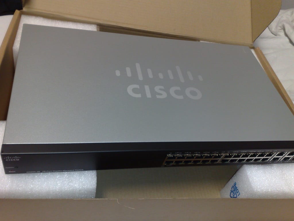
| Layer 2 switch | Layer 3 switch | |
|---|---|---|
| Decides using | MAC addresses | MAC addresses and IP addresses |
| Can route between VLANs | No | Yes |
| Has SVIs | No | Yes |
| Cost | Lower | Higher |
An SVI, switched virtual interface, is an IP address that belongs to the switch itself, inside a specific VLAN. It is a virtual port that lives in a VLAN rather than on a physical cable.
Why this matters enormously: an SVI is how a switch becomes the default gateway for a VLAN. Give the switch an SVI of 10.50.0.1 in the management VLAN, and every host in that VLAN can use 10.50.0.1 as its gateway, and the switch will route their traffic to other VLANs.
Without an SVI, a VLAN is an island. Hosts inside it can reach each other and nothing else. This is exactly the mechanism CloudStack expects for the management network gateway.
Top of rack design
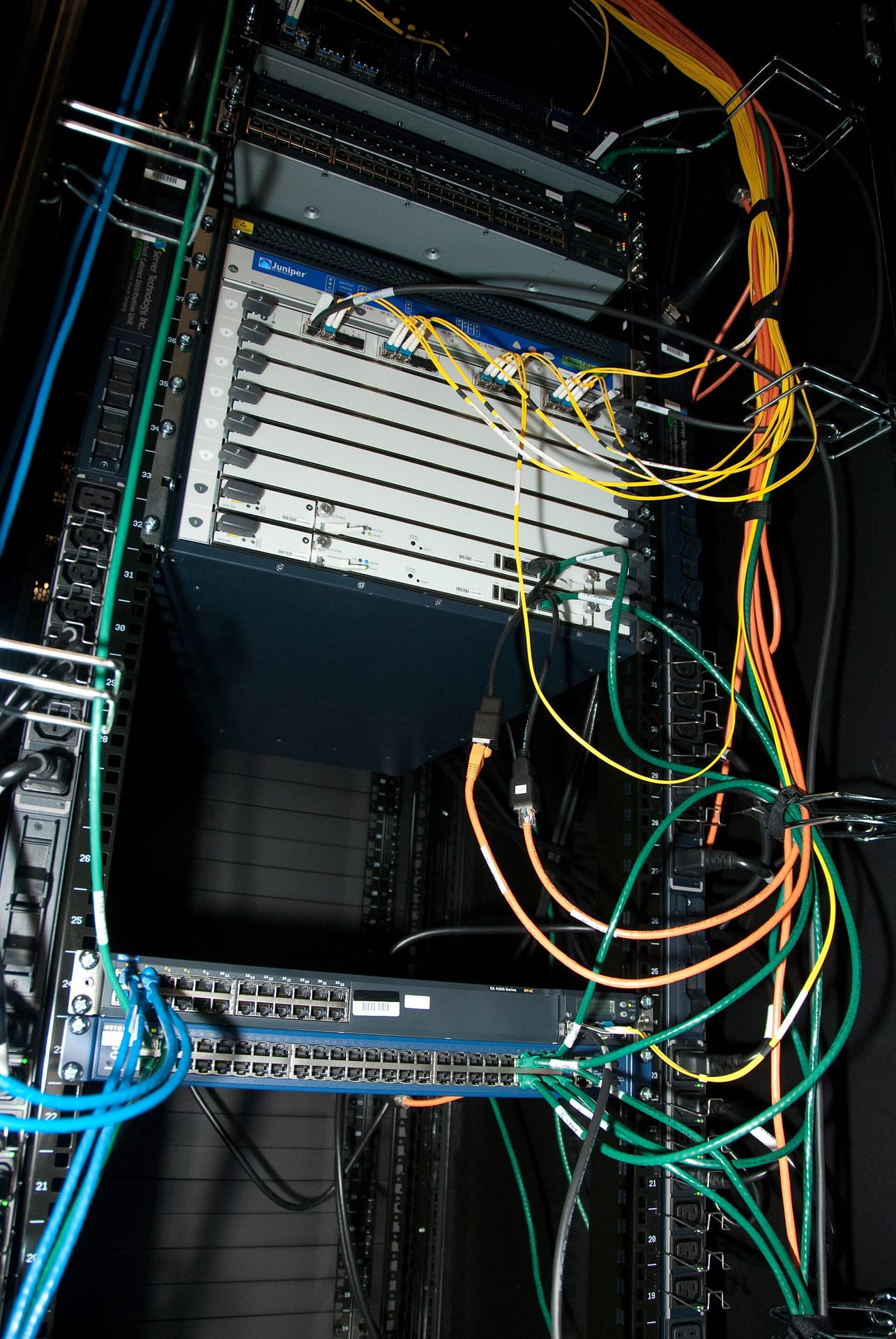
Top of rack means each cabinet has its own switch, and every server in that cabinet home runs to it with a short cable. Only the switch uplinks leave the cabinet.
| Property | Why it wins |
|---|---|
| Short cables | Cheap, DAC capable, easy to manage, easy to trace |
| Few cables leave the cabinet | Only uplinks cross between cabinets, so inter cabinet cabling stays sane |
| Fault domain matches the cabinet | A switch failure affects that cabinet, which is a boundary you can reason about |
| Grows one cabinet at a time | Adding a cabinet means adding a switch, not re cabling the room |
At launch we have one top of rack switch. That switch is a single point of failure for the entire rack, and no amount of server redundancy behind it changes that. If it dies, everything in the cabinet is unreachable.
We write that down, monitor the switch properly, keep a configured spare if budget allows, and plan the redundant pair as an explicit upgrade. What we do not do is describe a single switch as a best practice. The honesty rule from Volume 0 applies: a documented risk is engineering, an undocumented one is negligence.
CloudStack's reference topology, and the collapse we make at our scale
CloudStack documents a specific reference shape, and it is worth stating precisely because Doc 5 depends on it.
| CloudStack layer | What the reference design expects | What we do in one rack |
|---|---|---|
| Pod level access switch | A layer 2 switch that trunks all relevant VLANs to every host | Our ToR switch does this |
| Zone level layer 3 switch | Routes between networks and acts as the management network gateway | Our ToR switch also does this, via an SVI |
At our scale these two roles collapse into one device, and that is fine, provided you understand that you have collapsed them. A layer 3 capable ToR switch serves as both the pod access switch and the zone gateway. The reason to know this is that when you read CloudStack documentation describing two separate switches, you should be able to map it onto your one box rather than assuming you are missing hardware.
The switch buying checklist
| Feature | Why it is non negotiable |
|---|---|
| 802.1Q VLAN tagging | Section 6. Without it there is no multi tenancy at all. |
| Trunk ports carrying many VLANs | A hard CloudStack requirement, covered in section 6 |
| SVIs and inter VLAN routing | So the switch can be the management gateway |
| LACP, 802.3ad | Section 7, for bonded host uplinks |
| MLAG or stacking | Needed later for a redundant pair that a single host can bond across |
| Jumbo frame support, 9000 MTU | Section 7, for the storage VLAN |
| DHCP snooping and dynamic ARP inspection | The ARP spoofing defence promised in Doc 1, enforced in Doc 4 |
| RA guard | The IPv6 equivalent, promised in Doc 2 |
| Port security and storm control | Limits the damage one misbehaving tenant can cause |
| sFlow or NetFlow | Traffic visibility. You cannot investigate what you never recorded. |
| Dedicated management port | Section 8. Managing a switch through the network you are reconfiguring is how you lock yourself out. |
| Serial console port | The last resort when everything else is unreachable |
Oversubscription, in plain arithmetic
A restaurant has a hundred seats and a kitchen that can cook twenty meals at once. That is five to one oversubscription, and it works perfectly well because not everybody orders simultaneously.
A switch is the same. Suppose eight servers each connect at 10 Gbps, which is 80 Gbps of possible traffic into the switch. The switch has two 10 Gbps uplinks, so 20 Gbps out.
That is 4 to 1 oversubscription, and it is completely reasonable, because those servers are not all sending at full rate to the outside world at the same moment.
What actually matters is which traffic crosses the uplink. Server to server traffic inside the cabinet, including the storage traffic between hypervisors and the NFS node, never touches the uplink at all. So the ratio you care about is not total port capacity, it is the traffic that genuinely has to leave. Keep storage local to the cabinet and your oversubscription ratio stops mattering nearly as much.
6. VLANs: from concept to configured
The analogy: coloured stickers on the mail
You have one building, one corridor, and one mail trolley. But you have five departments, and department mail must never be delivered to the wrong department.
So you put a coloured sticker on every envelope. The trolley carries all colours down the same corridor. At each department door, only that colour is handed over.
A VLAN is the colour. The sticker is the 802.1Q tag. The corridor is the physical cable. And the whole point is that many separate networks share the same wire without ever mixing.Access port: a port belonging to exactly one VLAN. Frames arrive and leave untagged, because the device plugged in does not know VLANs exist. The department door.
Trunk port: a port carrying many VLANs, where frames are tagged so the other end can tell them apart. The corridor with the trolley.
Native VLAN: the one VLAN on a trunk whose frames travel untagged. The envelope with no sticker, where both ends have to already agree which department it belongs to.
The native VLAN, and why mismatches produce baffling failures
At first I found the native VLAN pointless, and here is the trick that made it click, along with the reason it is dangerous.Untagged frames on a trunk have to belong to something. The native VLAN is that something. It exists so a trunk can also carry traffic from a device that does not tag.
Now the danger. Suppose the switch thinks the native VLAN is 1, and the server thinks it is 10. The server sends an untagged frame meaning "this is VLAN 10 traffic." The switch receives it untagged and concludes "this is VLAN 1 traffic." The frame is now silently in the wrong network.
A native VLAN mismatch means traffic crosses a segmentation boundary without anything logging it or blocking it. There is no error. Both sides believe they are configured correctly. The frame simply arrives in a network it was never supposed to reach.
In a hosting environment where VLANs are how we keep tenants apart, that is a tenant isolation failure produced by a one line configuration disagreement.
The discipline: set the native VLAN explicitly on both ends of every trunk, use the same value everywhere, and never leave it at the vendor default. CloudStack reference designs commonly put hypervisor management on an untagged VLAN, which makes getting this right on the host trunks a launch requirement rather than a nicety.
The hard CloudStack requirement people miss
This is the single most common cause of a CloudStack deployment that installs cleanly and then behaves strangely, so read it twice.
The access switch must trunk all relevant VLANs to every compute host. Not just management and guest. The public VLAN too, on every host.
Why, when an external firewall handles guest gateways? Because CloudStack system VMs run on the hypervisors, and two of them need the public network directly:
The Secondary Storage VM needs public network access to fetch templates and ISOs from the internet.
The Console Proxy VM needs public network access so customers can reach their VM consoles from a browser.
Those system VMs can be started on any host in the cluster. So if even one host is missing the public VLAN on its trunk, everything works fine until a system VM happens to start on that host. Then console access or template downloads break, intermittently, in a way that looks like a CloudStack bug and is actually a switch port configuration.
Trunk every relevant VLAN to every host, identically. Uniformity is the requirement.
The VLAN numbering scheme we commit to
Numbers with meaning, and deliberate gaps for growth.
| VLAN ID | Name | Subnet | Gateway | Purpose |
|---|---|---|---|---|
| 10 | oob | 10.50.10.0/24 | OOB switch only | BMC and IPMI. No route anywhere. Section 8. |
| 20 | mgmt | 10.50.0.0/24 | 10.50.0.1 on the ToR SVI | Hypervisor management, CloudStack management servers, system VM management |
| 30 | storage | 10.50.1.0/24 | None, deliberately | NFS traffic. Jumbo frames. Section 7. |
| 40 | public | Our public range | Edge firewall | CloudStack public traffic. Trunked to every host. |
| 50 | dmz | 10.50.5.0/24 | Edge firewall | Internet facing platform services |
| 100 to 999 | guest-pool-1 | Allocated per network | CloudStack Virtual Router | Guest VLAN pool. CloudStack allocates from this range. |
| 1000 to 1999 | Reserved | Second guest pool, or a second zone | ||
| 1 | Unused, on purpose | Vendor default, so we never use it for anything real |
The storage VLAN has no gateway. This is deliberate, not an omission. Storage traffic never needs to leave its own VLAN, so giving it a gateway would only create a path for it to be reached from elsewhere. No gateway is a security control implemented by absence.
VLAN 1 is left unused. It is the default on essentially every switch, which means it is where mistakes land. An unconfigured port typically ends up in VLAN 1. If VLAN 1 carries nothing, then a mistake results in a port that reaches nothing, which is the failure mode you want.
Guest VLAN pool sizing, and the ceiling
A VLAN tag is 12 bits, which gives 4096 values, with two reserved. So you have roughly 4094 usable VLAN IDs, in total, across the whole layer 2 domain.
In CloudStack's isolated network model, each guest network consumes one VLAN. So the size of your guest VLAN pool is a direct cap on how many guest networks can exist simultaneously in that zone.
Our pool of 100 to 999 gives 900 guest networks. That is comfortably beyond the starter business plan and it is not unlimited. When you approach the ceiling, the answer is not a bigger VLAN range, because there is not one. The answer is VXLAN, which uses a 24 bit identifier and gives roughly 16 million segments.
VXLAN is the correct scale answer and it is not free: it adds encapsulation overhead that eats into your MTU, which is the subject of the next section, and it adds operational complexity. We start with VLANs, document the ceiling, and treat crossing it as a planned project rather than an emergency.
Some vendors offer protocols that automatically propagate VLAN configuration between switches. They sound helpful and they are a genuine hazard, because a mistake on one switch propagates to all of them at machine speed.
We configure VLANs explicitly on each device, from version controlled configuration, in keeping with the Terraform and GitOps model from Volume 0. Explicit and boring beats automatic and surprising.
7. Bonding, redundancy, and MTU
The analogy: two ropes instead of one
You need to hold a weight. One rope might snap. So you use two.
Now there are two genuinely different ways to use two ropes. You can use one and keep the other slack as a spare, or you can share the load across both. The first is simple and wastes half your capacity. The second doubles your capacity and requires that both ends of both ropes are tied correctly.
That is exactly the choice between active backup bonding and LACP, and there is no universally right answer. There is only the answer that matches the switch you actually bought.| Active backup, mode 1 | LACP, 802.3ad, mode 4 | |
|---|---|---|
| How it works | One NIC active, the other idle until the active one fails | Both NICs active, traffic distributed across them |
| Usable bandwidth | Half of what you installed | All of it, in aggregate |
| Switch configuration needed | None. The switch does not need to know. | Required on both ends, and they must agree |
| Can span two separate switches | Yes, trivially | Only if the switches support MLAG or stacking |
| Failure behaviour | Very simple and predictable | Fast, and more moving parts |
| Right choice when | You have one switch, or two independent ones | You have an MLAG pair or a stack |
We launch with one top of rack switch. Therefore we use active backup.
Here is the trap that catches people. With one switch, LACP would give us double the bandwidth and zero additional resilience, because both links terminate on the same box. If that switch dies, LACP does not save you. So LACP on a single switch buys throughput while adding a configuration dependency, and at launch throughput is not our constraint.
When the redundant pair with MLAG arrives, then LACP becomes correct, because at that point the two links genuinely terminate on two independent devices and the bond survives losing one.
Match the bonding mode to the switch topology, not to the bigger number in the datasheet.MLAG, multi chassis link aggregation, lets two physically separate switches present themselves to a connected server as if they were one switch.
That is what makes the good version possible. The server runs a single LACP bond, one link to each switch, and it does not know or care that they are two boxes. Lose a switch entirely and the bond keeps running at half capacity with no reconfiguration and no failover event on the host.
Vendors call it MLAG, VPC, MC-LAG, and other names. Whatever it is called, it must be on the buying checklist, because without it a redundant switch pair cannot carry a single bonded host.
Naming discipline, and the CloudStack requirement hiding in it
This is not a style preference. It is a functional CloudStack requirement, and violating it produces a failure that appears much later and looks unrelated.
Live migration moves a running VM from one host to another. To do that, CloudStack must attach the VM's network interfaces to the same named bridge on the destination host.
If kvm-host-01 calls its guest bridge cloudbr1 and kvm-host-02 calls it cloudbr2, then everything works perfectly right up until the first migration attempt, which fails. Or worse, it succeeds and attaches to the wrong network.
Every host in a cluster uses identical interface, bond, and bridge names. Write them into the build automation so a human never types them, and verify them in section 10.
Read that first output like a checklist. Bonding Mode confirms you got the mode you intended. MII Status: up on both slaves means both cables are genuinely live, which catches the case where you built a bond on a cable nobody plugged in. Speed on each slave catches a link that negotiated down to 1 Gbps because of a bad cable. And Link Failure Count climbing over time is a cable or optic that is failing intermittently, which is exactly the fault you want to catch before it becomes an outage.
MTU, and the three layers you must plan separately
MTU came up in Doc 1 as the doorway height. Here are the actual numbers, and the thing to understand is that MTU is not one setting, it is three separate decisions.
| Where | Value | Reasoning |
|---|---|---|
| Management VLAN | 1500 | Standard. There is no benefit to changing it and there is risk. |
| Public and guest VLANs | 1500 | Must be standard. This traffic goes to the internet, where 1500 is the assumption. |
| Storage VLAN | 9000, jumbo frames | Bulk NFS transfers, entirely inside our layer 2, measurable efficiency gain |
| Physical underlay, if VXLAN later | 9000, or at minimum 1600 | Must exceed guest MTU plus encapsulation overhead |
Every frame carries protocol headers. Those headers are roughly the same size regardless of how much data the frame carries.
With a 1500 byte MTU, moving a gigabyte of data takes on the order of 700,000 frames. With a 9000 byte MTU, the same gigabyte takes about 117,000 frames.
That is six times fewer frames, which means six times fewer headers to process and six times fewer interrupts for the CPU to service. On a storage network moving VM disk images and snapshots, that is a genuine and measurable reduction in CPU overhead and latency.
Why not use 9000 everywhere then? Because it only helps for large sustained transfers, and it requires every device in the path to agree. Internet traffic cannot agree, because you do not control the internet. So jumbo frames belong exactly where we put them: a dedicated, closed VLAN carrying bulk transfers between devices we own.
Every single device in the layer 2 path must be configured for the same MTU. Both hypervisors, the storage node, the switch, and every VLAN interface involved. One device left at 1500 breaks it.
And here is why this is the cruellest fault in the document. An MTU mismatch does not look like a network problem.
Small transfers work perfectly. Pings succeed. SSH is fine. Everything you instinctively test passes.
Large transfers stall, or run absurdly slowly, or hang and time out.
So the symptom is "our storage is slow" or "template downloads hang", and the team spends two days investigating disks, NFS tuning, and CPU load, because nobody suspects the network when ping works.
I want you to remember one sentence: if small things work and big things do not, check MTU first. It will save you a day at least once in your career.
-M do means do not fragment. This is essential. Without it the kernel quietly chops the packet up and the test passes even when the path cannot carry the size, which tells you nothing.
-s 8972 is the payload size. Add 28 bytes of IP and ICMP header and you get exactly 9000, the MTU. So this packet is the largest one that can possibly fit.
The first ping succeeding proves the entire layer 2 path carries 9000 byte frames. That is the real test.
The second command failing at 8973 is not a problem, it is the confirmation. It proves you found the exact ceiling rather than getting lucky with a smaller size. A test that only ever passes has not told you where the limit is.
Run this between every pair of devices on the storage VLAN, before CloudStack is installed. It is in the section 10 checklist.
When VXLAN enters the picture, the overlay wraps every guest frame in additional headers, costing roughly 50 bytes.
So if the guest expects a normal 1500 byte MTU, the physical underlay must carry at least 1550, and in practice you want margin, so people commonly use 1600 as a floor or simply run the underlay at 9000.
The failure mode if you skip this is that guest VMs cannot pass full sized packets, which presents as the same maddening "small things work, big things fail" symptom, this time reported by customers rather than found by you. Full requirements land in Doc 5.
8. Out of band management, the lifeline
The analogy: the spare key with your neighbour
You leave a spare key with a trusted neighbour. Not because you expect to lock yourself out, but because the day you do, the alternative is a locksmith and a broken door.
Out of band management is that spare key, and here is the thing I want to be blunt about: you will need it. Not might. Will. Every engineer who has configured a network at any depth has, at least once, applied a change that severed their own connection to the device they were changing. The competent ones had a way back in.
A BMC, baseboard management controller, is a small independent computer built onto the server's motherboard. It has its own processor, its own memory, its own firmware, and critically its own network port.
It runs whenever the server has power, even when the server is switched off. Think of it as the night watchman who stays awake in a closed building.
IPMI is the standard protocol for talking to a BMC. Vendors then brand their implementations: iDRAC on Dell, iLO on HPE, XClarity on Lenovo, IPMI generically on Supermicro. Same concept, different names and licence tiers.
What it lets you do, and this is the part worth internalizing: power the server on and off, watch the console as if you were standing in front of it including the BIOS and the boot messages, mount an ISO over the network to reinstall the operating system, read fan speeds, temperatures, and power supply health, and read the hardware event log to find out what failed.
All of that with the operating system completely dead. That is why it is called out of band: it is management that does not travel over the network the server itself uses.
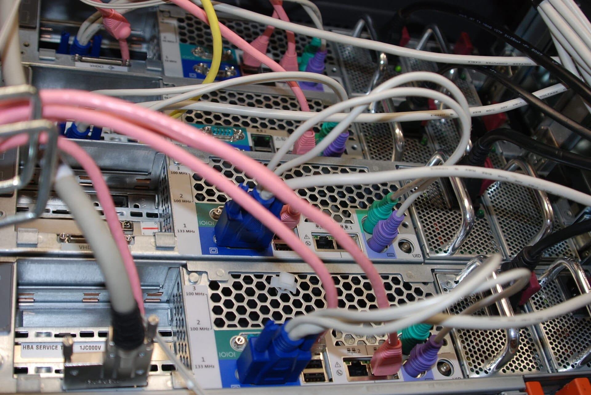
Go back and look at the server rear panel photograph in section 3. Among those ports is a dedicated management port, physically separate from the data NICs. That single port is the difference between fixing a broken host from your desk and driving to the datacenter.
What OOB covers, and the small switch that serves it
| Device | Its OOB interface | Where it plugs |
|---|---|---|
| KVM compute hosts | Dedicated BMC port, IPMI | oob-sw-01, VLAN 10 |
| CloudStack management servers | Dedicated BMC port | oob-sw-01, VLAN 10 |
| Storage node | Dedicated BMC port | oob-sw-01, VLAN 10 |
| Top of rack switch | Management port, plus serial console | oob-sw-01, VLAN 10 |
| Edge firewall | Management port, plus serial console | oob-sw-01, VLAN 10 |
| The OOB switch itself | Serial console, and colo provided OOB if available | The honest recursion problem, below |
If your OOB access runs through oob-sw-01, then what recovers oob-sw-01?
There is no clever answer. The chain has to terminate somewhere, and it terminates at something physical.
What we actually do: keep the OOB switch configuration deliberately trivial, essentially one flat VLAN and nothing clever, so there is almost nothing to break. Keep its configuration in version control so it can be restored quickly. Buy a serial console option from the colo if they offer one, which puts the last resort outside our own equipment entirely. And accept that in the worst case, the recovery path is remote hands with a laptop and a console cable, which is precisely why we asked about their response commitment in section 1.
Do not pretend this is solved. Know where the chain ends and how long that step takes.Isolation, which is the part people get wrong
Be very clear about the security picture here, because it is uncomfortable.
A BMC can power cycle the machine, mount arbitrary media, and watch the console. Anyone who controls a BMC controls the server completely and beneath the operating system, where none of your host security tooling can see them.
And BMC firmware has a genuinely poor security history. Default credentials, patches that arrive late or never, and vulnerabilities that keep appearing. Attackers know this, and BMCs are a well documented lateral movement and persistence target precisely because they survive an operating system reinstall.
Therefore the isolation rules are absolute, not preferences:Private addressing only, on VLAN 10, which appears in no public routing.
No route to the internet. None. Not for firmware updates, not for convenience. Updates arrive through a jump host.
No route to any tenant or guest network. Ever.
Reachable exclusively through a jump host or a VPN, with strong authentication and full session logging.
Default credentials changed on every device before it is racked, verified as a checklist item.
Never on a VLAN shared with anything else. A dedicated physical switch is cheap and the separation is worth more than the switch costs.
Here is the framing that makes this land for me: a compromised BMC is worse than a compromised operating system, because a reinstall does not remove it. It is the most privileged and least monitored surface in the rack. Treat it that way, and it becomes one of the controls we can actually demonstrate during the reviews described in security and trust posture.
The access runbook
| Question | Our answer |
|---|---|
| Who may reach OOB? | A named, short list of infrastructure engineers. Not a role. Names. |
| How do they reach it? | VPN, then jump host, then the OOB network. Two authenticated hops. |
| With what authentication? | Multi factor at the VPN, keys at the jump host, individual credentials per device |
| What is logged? | Every session, with who, when, which device, and what they did |
| How is access removed? | Part of the leaver process, tested rather than assumed |
| What is the break glass path? | Serial console, then colo remote hands, both documented with contact details and expected timings |
A runbook nobody has practised is a document, not a capability.
Rehearse this deliberately: during a maintenance window, have an engineer deliberately break the network configuration on a non production host, then recover it using only OOB. Time it. Write down every step that was unclear, every credential that was missing, and every assumption that turned out to be wrong.
Do it before you have customers, because the alternative is discovering the gaps during a real incident with an audience.
9. The physical network zone map, finalized
Volume 0 named the zones. Doc 5 will consume them. This is the authoritative table in between, and from here onward this is the version everything else references.
| Zone | VLAN | Subnet | Gateway | Addressing | MTU | What connects |
|---|---|---|---|---|---|---|
| WAN uplink | Untagged on the handoff | Assigned by the carrier | Carrier side | Static, from the carrier | 1500 | Colo handoff into the firewall outside interface |
| Edge and DMZ | 50 | 10.50.5.0/24 | 10.50.5.1, firewall | Static | 1500 | Internet facing platform services |
| Management | 20 | 10.50.0.0/24 | 10.50.0.1, ToR SVI | Static for infra, CloudStack pool for system VMs | 1500 | Hypervisor management interfaces, both CloudStack management servers, system VM management addresses |
| Public | 40 | Our allocated public range | Firewall | CloudStack public IP pool | 1500 | Trunked to every host. Virtual Routers, SSVM, CPVM. |
| Guest | 100 to 999 | Per guest network | CloudStack Virtual Router | Virtual Router DHCP | 1500 | Customer VM traffic, one VLAN per isolated network |
| Storage | 30 | 10.50.1.0/24 | None, deliberately | Static only | 9000 | Hypervisor storage interfaces and the NFS node |
| Out of band | 10 | 10.50.10.0/24 | None reachable from production | Static | 1500 | Every BMC, plus switch and firewall management ports |
Private and public networks require separate subnets. CloudStack advanced zones require distinct subnets for the private and public networks. This is not a recommendation you can economize on, and a deployment that shares them behaves incorrectly.
Storage needs its own subnet, and here is the actual reason. People assume the dedicated storage VLAN is purely about performance. Performance is a benefit. The requirement is that a hypervisor with two interfaces needs a way to decide which interface to send storage traffic out of, and it makes that decision from the routing table, which means the storage network must be a different subnet from the management network.
Put storage and management in the same subnet and the hypervisor will send storage traffic out whichever interface the routing table happens to prefer, which is usually the management one. Everything appears to work, your jumbo frames do nothing, and your storage traffic competes with management traffic. The separate subnet is what makes the interface separation real.
The buildable diagram
This replaces the executive sketch from Volume 0 with the version you could hand to an installer.
The three things to read off that diagram: every host trunk carries the identical VLAN list including 40, which is the CloudStack requirement from section 6. The OOB paths are dotted and terminate nowhere else, which is the isolation from section 8. And both power feeds enter the rack, which is section 3.
10. Install day and verification
The analogy: the pre flight checklist
A pilot with thousands of hours still reads the checklist aloud before every flight. Not because the knowledge is missing, but because under time pressure, humans skip steps, and the checklist is what catches that.
Install day is time pressured by definition. You have a booked window, possibly a drive or a flight, and a technician waiting. This is exactly the situation where a checklist outperforms competence.
The CloudStack community's own troubleshooting guidance says something worth repeating: in the vast majority of cases where a deployment misbehaves, the problem turns out to be the switching layer configured incorrectly.
Think about what that means for how you spend install day. If you install CloudStack on an unverified network, then every subsequent problem has two candidate causes, and you will spend your time reading CloudStack logs hunting for a bug that is actually a trunk port.
So we prove the network works while the network is the only thing that exists. Every test below runs before CloudStack is installed. Then when CloudStack does misbehave, you can genuinely say the network is not the cause, because you hold the evidence.
Everything on this list is far easier at your desk than in a cold aisle.
- Firmware updated on BIOS, BMC, NICs, and storage controllers, then recorded so every host matches
- BMC configured with a static address on VLAN 10, and default credentials changed
- BIOS settings applied identically on every host: virtualization extensions enabled, power profile set, boot order set
- Interface naming confirmed, so you know which physical port is which logical name before you cable anything
- Drives installed and the storage controller configured
- Labels printed for every device and every cable, then packed with the gear
- Configuration files staged in the repository for the switch, the firewall, and the host build
Once it is racked and you are behind schedule, this becomes a task for later, and later becomes never. A BMC sitting on your management network with vendor default credentials is the single most valuable thing an attacker can find, for exactly the reasons in section 8.
The as built document
The rack does not match the plan. It never does. Something was out of stock, a port was faulty, a cable was too short.
The as built document records what is physically there, and it gets written on install day while the details are in front of you, rather than reconstructed later from memory.
Contents: the final rack elevation with actual U positions, the cabling schedule with actual ports and labels, serial numbers and asset tags per device, firmware versions as installed, the final VLAN and subnet table, IP assignments including every BMC, the power feed assignment per device, and photographs of the front and rear of the rack.
Where it lives: in the repository, version controlled, beside the switch and firewall configurations. Not on someone's laptop, not in a shared drive nobody can find, and not in the head of whoever did the install. That is the zero tribal knowledge commitment from Volume 0, applied to hardware.
Take the photographs. Genuinely. A clear photo of the front and the rear of the rack, taken on install day, answers questions for years afterwards and costs thirty seconds. Every time somebody asks which port host 03 is in and you answer from your desk instead of calling remote hands, that photo has paid for itself again.
Labs and deliverables
| Deliverable | Format |
|---|---|
| Rack elevation | U by U layout with device names, weights, and power draw. Section 2 gives you the template. |
| Power budget sheet | Per device draw, totals, headroom, and A and B feed assignment, with the single feed survival row |
| Cabling schedule | Source device and port, destination device and port, media type, length, and the exact label text for both ends |
| VLAN and subnet table | The authoritative version from section 9, consumed by Doc 4 and Doc 5 |
| Switch configuration outline | Trunk ports, access ports, native VLAN, LACP groups, SVIs, and jumbo frame settings |
| Trunk verification test | Tagged interface ping plus the tcpdump capture proving the tag, per VLAN per host |
| MTU verification record | The do not fragment ping results between every pair of devices on the storage VLAN |
| Hardware requirements list | Switch, firewall, transceiver, and cable specifications for procurement, built from the section 5 checklist |
| OOB access runbook | The section 8 table filled in with real names, real paths, and a rehearsal date |
Honest tradeoffs we are documenting, not hiding
| Choice | Starter position | Scale position | What triggers the change |
|---|---|---|---|
| ToR switching | Single switch, documented as a single point of failure | Redundant pair with MLAG and LACP to hosts | First paying customer with an availability commitment |
| Edge firewall | Single appliance | High availability pair | Same trigger as the switch pair |
| Host uplinks | Two NICs bonded active backup, management and guest separated | Four NICs in two bonds, or 25G with overlay | Uplink utilization, or the arrival of an MLAG pair |
| Tenant isolation transport | VLAN per guest network | VXLAN with EVPN | Approaching the guest VLAN pool ceiling |
| Storage transport | Dedicated storage VLAN, NFS, jumbo frames, one node | Higher speed links, possibly Ceph with its own considerations | Storage IOPS or capacity metrics, not ambition |
| PDUs | Metered, at minimum | Switched, for remote power cycling | The first time you need a hard reboot and cannot get one |
We write the starter position down as a known risk, not as a pretend best practice. That is the same honesty rule Volume 0 used for the single firewall and single ToR, and it is the reason the tradeoff table has a trigger column. A risk with a documented trigger is a plan. A risk without one is just an excuse that ages badly.
Success criteria
You are done with this document when you can:
- Recognize and name every component in the photographs above, and explain what each one is for
- Hand a colo provider a rack elevation, a power request, and a cross connect request without hesitating
- Explain why every VLAN must be trunked to every hypervisor, including the public VLAN, and name the two system VMs that make it necessary
- Choose between LACP and active backup and defend the choice using the switch you actually bought
- State the MTU on each VLAN and prove it end to end with a do not fragment test
- Describe, step by step, how you regain control of a host whose network configuration you just broke
- Explain why the storage VLAN needs its own subnet, and why it has no gateway
Forget the list for a second. Here is the real one.
Someone hands you a photograph of the back of a rack. Can you name what you are looking at? The power supplies, the management port, the data NICs, the DAC cables, the transceivers, the patch panel, the cable management bars, and whether the person who built it split the power feeds.
If you can do that, you have the thing that separates someone who has worked with this hardware from someone who has read about it. That was the entire point of putting the photographs in.
This document is where the handbook stops being theory. Everything after it assumes a rack that a professional would be comfortable owning, and a set of decisions you can defend in a room with a vendor, an auditor, or a customer.
Next: Segmentation, firewalls & edge defense. The wires exist and the VLANs are defined. Now we decide who may talk to whom, and enforce it.